What are matching resistors?What are the functions of matching resistors?
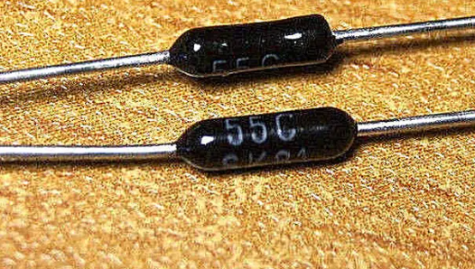
  In the design and manufacturing process of electronic products, PCB (Printed Circuit Board) board design is a crucial link. In PCB board design, the use of matching resistors plays a decisive role.  So, what exactly is a matching resistor? What role does it play in PCB board design? This article will provide an in-depth analysis of the importance and specific role of matching resistors in PCB board design.  What are matching resistors?Matching resistors refer to resistors that have nearly identical electrical characteristics, including resistance values, tolerance, and temperature coefficients. These resistors are specifically chosen and paired to ensure that the electrical properties across different parts of a circuit are as uniform as possible. This matching process is critical in applications where balance, precision, and stability are essential.  What are the functions of matching resistors?  1. Impedance matching  Impedance matching is the most direct and important role of matching resistors. In circuits with high-speed signal transmission, the integrity of the signal largely depends on whether the impedance of the circuit is matched.  If the impedances of the transmitter and receiver do not match, the signal will be reflected during transmission, resulting in signal distortion or even complete loss.  By reasonably setting matching resistors in the circuit, the impedances of the transmitting end and the receiving end can be matched, thereby reducing signal reflection and distortion and ensuring signal integrity and stability.  2. Terminal matching  In addition to impedance matching, matching resistors are also commonly used for termination matching. In long-line transmission or high-speed digital signal transmission, due to the inductance and capacitance effects of the line, the signal may ring at the end of the transmission line.  By connecting a matching resistor in parallel to the ground at the end of the transmission line or connecting a matching resistor to VCC (positive power supply), the reflected signal can be effectively absorbed, the ringing phenomenon eliminated, and the signal transmission quality improved.  3. Voltage division and current limiting  In addition to the above two main matching functions, matching resistors can also play the role of voltage dividing and current limiting in the circuit.  In some situations where precise control of voltage or current is required, precise adjustment and control of voltage or current can be achieved by reasonably setting the resistance of the matching resistor.  In addition, in some situations where sensitive devices need to be protected from excessive current impacts, matching resistors can also be used as current-limiting resistors to protect the circuit.  What’s the application of matching resistors?  ● Amplifier Circuits:  In amplifier circuits, matching resistors are often used in critical stages to maintain balance and symmetry. Balanced resistors help ensure that signals passing through the amplifier are accurately amplified without distortion. This is particularly important in audio applications where fidelity is a key consideration.  ● Voltage Divider Networks:  In voltage divider circuits, matching resistors are employed to divide an input voltage into precise fractions. Any mismatch in resistor values can result in inaccurate voltage division, leading to errors in the output signal. Precision is crucial in applications like sensor networks and measurement devices.  ● Bridge Circuits:  Wheatstone bridge circuits, commonly used in precision measurement applications, rely on the accurate matching of resistors. This ensures that the bridge is balanced, providing accurate and stable readings in applications such as strain gauge sensors and temperature sensors.  ● Feedback Networks:  Matching resistors play a crucial role in feedback networks of operational amplifiers. In circuits employing negative feedback, the resistors are often matched to maintain a stable and predictable gain, contributing to the overall performance and reliability of the amplifier.  Principles for selecting matching resistorsWhen selecting matching resistors, certain principles need to be followed to ensure circuit performance and stability.  First, the resistance of the matching resistor must be determined based on the operating frequency of the circuit and the characteristic impedance of the transmission line. Secondly, the power handling capacity of the matching resistor should be considered to ensure that it will not be damaged due to overheating during operation.  In addition, factors such as the accuracy and stability of the matching resistors need to be considered to ensure that their impact on circuit performance is minimized.
Release time:2024-02-26 16:31 reading:1841 Continue reading>>
What is capacitor polarity?  How do you determine the polarity of a capacitor?
  Capacitor is an electronic element which is passive in nature. This electronic element is utilized for storing charge. The capacitors are of two types: Polarized and non-polarized. Capacitor polarity is defined as having either negative or positive charge on the capacitor. The capacitors with no signs or charge are known as non-polarized capacitors. This element consists of two leads or ends. One off the end is positive or anode and the other is cathode or negative.  What is capacitor polarity?  Capacitor polarity can be elaborated as having a negative or positive influence or charge on the terminals of the capacitor. Numerous methods are advised for finding the capacitor polarity. The capacitors polarity can be distinguished by looking at its terminal’s length. The one with longer lead is supposed to be anode or negative terminal of the capacitor while the one with shorter lead is positive and one with large length is negative. Non-polar capacitors have nothing relevant to the specific format when it is to be connected within a circuit.  Is capacitor always negative?  No, the capacitor is not always negative; however, when connecting the capacitor with a source of voltage, the charge or potential of the capacitor can be determined. Capacitor polarity is needed to be considered because if ignored then its layer of oxide becomes vulnerable to damage and avalanche current is drawn by capacitor making it out of work or even destroyed.  Are capacitors polarity sensitive?  A total of three layers are present in capacitor when its fabrication process is considered. The layer which is for insulation is known as dielectric. It is in the middle of the anode and cathode which are metallic sheets. The anode and cathode are always in parallel to each other. The insulator is supposed to be in the middle of the sheets of metal. The main purpose of dielectric is that it separates the electrodes.  The polarized capacitors are always polarity sensitive. The basic rules of the circuit theory must be obeyed in order to allow capacitors to work. For installation of a polar capacitor within a circuit, its polarity is surely to be considered. Capacitor polarity if ignored can cause damage to the circuit and to the capacitor as well.  How do you determine the polarity of a capacitor?  There are a number of ways through which the capacitor polarity can be determined. During the process of fabrication of capacitor, its polarity is to be taken care off. Some kinds of capacitors are having bars for its positive and negative terminals identification.  The one with longer lead is supposed to be anode or positive terminal of the capacitor while the one with shorter lead is a cathode or negative terminal. However, sometimes the terminals have equal length and it gets very difficult to identify the terminal. Working out on the polarity of capacitor is of great importance as it will destroy the capacitor or even entire circuit if connected in wrong manner when the capacitor is polar in nature.  Which capacitor must be connected with the correct polarity?  The polar capacitors must be connected in a proper way within the circuit in accordance to the polarity of the circuit. The polarized capacitors never gets damaged with the heat when soldering is in progress.  What are the examples of capacitor polarity?  The following are some major and famous types of capacitor polarity.  Electrolytic capacitors  Electrolytic capacitors are widely utilized kind of capacitors. Such are of polar kind and are manufactured in two styles i.e., axial and radial. Both terminals of radial capacitors are on same side. Both sides of axial capacitors are on opposite sides. The radial capacitors are cheaper in price and also small in size.  Tantalum capacitors  Capacitor polarity is mentioned on tantalum capacitors too. These capacitors are having lower voltage and current ratings. These are of small size. Such capacitors are very expensive. Tantalum capacitors are only used for high demand and sensitive applications.  Ceramic capacitors  These are often in round shape and its ratings and values are mentioned on it. The length of its leads or terminals is answer to its positive and negative terminal like electrolytic capacitors. The applications of ceramic capacitors comprise of RF devices.  Super capacitors  Ultra-capacitor is another name given to super capacitor and such capacitors may range up to certain thousand Farads. Such elements are used in applications like consumer electronics.  Film capacitors  Such capacitors are in square or rectangular shape. Film capacitors are cheap and economical. These elements are having less frequency response. These are small in size and are utilized in most of the electronic equipment.  How do you check capacitor polarity with a multi-meter?  For determining the capacitor polarity with the help of a multi-meter, the device is to be set at higher resistance measuring range up to 1 Mega Ohms. The multi-meter is then to be connected to the legs of capacitor for its terminal identification. The red lead of multi-meter is to be connected to positive terminal while black lead is to be attached to negative terminal. Monitoring the meter to start reading from zero and slowly moving to measure higher resistance until infinity is reached.  What happens if you reverse the polarity of a capacitor?  In case if the polarity of the capacitor is reversed then the capacitor may get damaged because of the flow of high amount of current through it. Another possibility is that it may create a short-circuit destroying entire circuit.
Release time:2024-02-23 14:00 reading:2047 Continue reading>>
AIR Partners with Nidec to Develop Customized eVTOL Motor for AIR ONE Production Model
  AIR, creator of eVTOLs for the consumer market, today announced its partnership with Nidec Motor Corporation, a leading manufacturer of commercial, industrial, and appliance motors and controls, to develop the motor for the production model of AIR’s two-seater eVTOL (electric vertical takeoff and landing) aircraft, AIR ONE. The two companies will design and develop a motor specifically for mid-sized eVTOL aircraft, ultimately filling a void in the burgeoning AAM (advanced air mobility) industry.  “AIR ONE”  This collaboration marks a significant step towards the future of aviation and the mass production of consumer eVTOL aircraft for the very first time. Nidec, an industry veteran of fifty years and among the world’s largest electric motor manufacturers, will work with AIR to develop an efficient motor customized to support the single-charge journeys of up to 100 miles that AIR ONE offers. Funded by the BIRD Energy program of the BIRD Foundation (Israel-U.S Binational Industrial R&D Foundation) to support innovative joint clean energy U.S.-Israel collaborations, the resulting enhanced-efficiency motor will be incorporated into AIR ONE’s continued flight testing and eventually into AIR’s production practices.  “The motor represents the heart of any vehicle. It’s thrilling to partner with Nidec, a pillar of market excellence, to advance the production of AIR ONE,” said Rani Plaut, CEO and co-founder of AIR. “Not only does this partnership represent a major turning point for the AAM industry as a whole, but it also specifically paves the way to fulfilling AIR’s mission and the dream of personal flight.”  “We’re excited to merge Nidec’s motor expertise and global manufacturing capabilities with AIR’s revolutionary eVTOL to deliver advanced motor capabilities to the individual consumers who wish to fly,” said Vincent Braley, CEO of Nidec Aerospace. “Nidec’s uncompromising quality standards and technical capabilities have been trusted implicitly for decades throughout industries, and we’re ecstatic to create an aerospace centric motor, designed for safety, that AIR ONE customers know they’ll be able to depend on.”  The partnership is the latest milestone for AIR, which announced its participation in the U.S. Air Force’s prestigious AFWERX Agility Prime program last month to drive flight testing and additional eVTOL R&D efforts in the United States. Previous full-scale, full-weight flight tests, including hover-to-cruise and cruiseto-hover transitions, prove AIR’s status as an industry leader, flying ahead of the curve on these milestones. With over 1,000 AIR ONE vehicles reserved via preorder and a waiting list, AIR plans to deliver the first batch of aircraft to consumers following aircraft certification.  About AIR  AIR is revolutionizing everyday mobility for everyday people, empowering individuals to seize the power of personal flight. Combining aerospace innovation with the maturity of automotive technology and uncompromising safety standards powered by proprietary fly-tech, AIR's first-of-its-kind eVTOLs for personal use offer the ground-breaking opportunity to easily "drive the sky." Founded by Chen Rosen, Netanel Goldberg and Rani Plaut, based in the green fields of Pardes Hanna, near Tel Aviv, AIR is paving the way for a cleaner, more thrilling future of mobility, affording everyone the freedom to fly.
Key word:
Release time:2024-02-22 13:14 reading:2925 Continue reading>>
Ceramic capacitors vs. electrolytic capacitors – what are the differences?
  In the vast realm of electronic components, capacitors stand as fundamental devices for storing and releasing electrical energy. Among the diverse spectrum of capacitors available, two prominent types—ceramic capacitors vs. electrolytic capacitors —emerge with distinct characteristics, applications, and performance attributes. Delving deeper into their nuances is crucial for discerning engineers, hobbyists, and electronic enthusiasts aiming to optimize circuit designs and performance.  What is capacitor?Capacitors, as passive electronic components, are pivotal in numerous circuit applications. They consist of two conductive plates (electrodes) separated by a dielectric material. When a voltage is applied across these plates, they accumulate and store electrical charge, which can be discharged when required, aiding in various electrical functions within circuits.  Ceramic Capacitors  Characteristics:  Ceramic capacitors are renowned for their reliability, stability, and an extensive range of capacitance values. These capacitors utilize ceramic materials with a metal layer serving as the electrodes. They are available in diverse shapes and sizes, encompassing both surface-mount (SMD) and through-hole configurations.  Advantages:  Low ESR (Equivalent Series Resistance): Ceramic capacitors are known for their low ESR, enabling swift responses to voltage fluctuations and changes.  High Frequency Response: Their minimal parasitic effects make ceramic capacitors highly suitable for high-frequency applications.  Stability and Temperature Performance: They exhibit commendable stability across temperature variations, ensuring consistent performance.  Limitations:  Capacitance Variability: Ceramic capacitors may demonstrate significant variations in capacitance concerning voltage and temperature fluctuations.  Piezoelectric Effect: Certain types of ceramic capacitors exhibit the piezoelectric effect, generating electrical charge under mechanical stress.  Applications:  Ceramic capacitors find extensive usage in high-frequency circuits, decoupling applications, signal filtering, and as crucial components in power supply bypass circuits.  Electrolytic Capacitors  Characteristics:  Electrolytic capacitors employ an electrolyte as the dielectric material between their plates. They primarily exist in two major types: aluminum electrolytic and tantalum electrolytic capacitors.  Advantages:  High Capacitance: Electrolytic capacitors offer substantially higher capacitance values compared to ceramic capacitors, making them suitable for applications requiring significant energy storage.  Cost-Effectiveness: They are generally more cost-effective for higher capacitance requirements.  Polarity: Electrolytic capacitors are polarized, rendering them ideal for DC circuit applications.  Limitations:  Higher ESR: Electrolytic capacitors typically exhibit higher ESR compared to ceramic counterparts.  Temperature and Lifespan Sensitivity: They are more susceptible to temperature variations and have a limited operational lifespan compared to ceramics.  Applications:  Owing to their higher capacitance values, electrolytic capacitors find applications in power supply filtering, audio systems, and situations demanding substantial energy storage capabilities.  Ceramic capacitors vs. electrolytic capacitors – what are the differences?Capacitance Range:  Ceramic capacitors offer a lower capacitance range in comparison to electrolytic capacitors. For high-frequency applications or instances necessitating low ESR, ceramic capacitors are preferred. However, for applications requiring higher capacitance values, electrolytic capacitors become the go-to choice.  Frequency Response:  Ceramic capacitors exhibit remarkable performance in high-frequency applications due to their minimal parasitic effects and low ESR. Hence, they are particularly well-suited for RF circuits and high-speed digital designs. On the other hand, electrolytic capacitors, with higher ESR, are more adept in low-frequency applications.  Size and Form Factor:  Ceramic capacitors possess a smaller form factor and are available in compact surface-mount packages, making them ideal for space-constrained designs. In contrast, electrolytic capacitors are relatively larger and are commonly utilized in applications where space availability isn’t a limiting factor.  Cost Considerations:  Ceramic capacitors offer cost-effectiveness for lower capacitance values, while electrolytic capacitors provide cost advantages for applications requiring higher capacitance values, making cost a crucial factor in the selection process.  ConclusionIn conclusion, while both ceramic and electrolytic capacitors exhibit distinct attributes and serve varied purposes, their selection profoundly impacts the performance and reliability of electronic circuits across diverse applications. The optimal choice hinges on an intricate understanding of specific application requirements, encompassing capacitance range, frequency response, size constraints, cost considerations, and voltage stability.
Key word:
Release time:2024-02-20 11:50 reading:1494 Continue reading>>
ROHM's New Zero-Drift Op Amp with High Accuracy Regardless of Temperature Changes
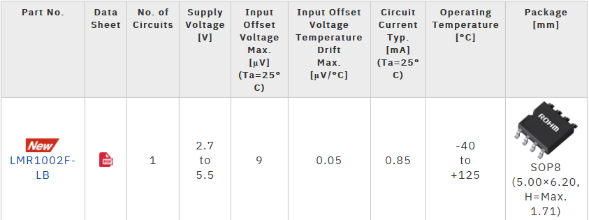
  ROHM has developed a zero-drift operational amplifier (op amp) - the LMR1002F-LB. It is designed for industrial and consumer electronics devices and minimizes both input offset voltage and input offset voltage temperature drift. Capable of accurately amplifying output signals from sensors installed in various measurement devices, this new op amp is ideal for current sensing applications such as power control inverters and temperature/pressures/flow/gas detectors.  As automotive and industrial equipment become more sophisticated and application control requirements are more precise, environmental sensors are increasingly being used to quantify temperature, pressure, and gas concentrations such as carbon dioxide to foster a sustainable society. However, sensor signals are so small that amplification is necessary, and if a general op amp with 1mV offset voltage is used to amplify the sensor signal by a factor of 1,000, for example, the offset voltage also increases by this amount - resulting in a voltage error of 1V (1,000mV) in the signal output. At the same time, input offset voltage temperature drift, which varies according to temperature and time, is difficult to compensate for.  In response, ROHM developed a zero-drift op amp that addresses these problems by leveraging proprietary analog circuit technology - cultivated over many years. The LMR1002F-LB is ROHM’s first zero-drift op amp using the chopper method. In contrast to conventional low-offset op amps featuring a typical input offset voltage of 150µV (Max.), ROHM’s new product limits input offset voltage to just 9µV (94% lower). This eliminates the need for peripheral components or software to adjust the input offset voltage, reducing both design person-hours and costs. On top, input offset voltage temperature drift is just 0.05µV/°C (Max.) in the operating temperature range of -40°C to +125°C - the lowest among ROHM’s op amps. Enabling accurate amplification of measured sensor signals without being affected by environmental changes such as temperature contributes to high accuracy control of industrial equipment in factories. This, coupled with a wide supply voltage range of 2.7V to 5.5V and rail-to-rail input/output, make it ideal for a variety of industrial applications.  Going forward, ROHM will continue to improve the performance and expand its lineup of zero-drift op amps. Moreover, ROHM will work to improve the performance of op amp lineups by reducing noise and offset - while increasing power savings, and expand the power supply voltage range demanded in the automotive and industrial equipment markets. The overall goal: contributing to solving social issues through higher accuracy application control.      Product Lineup  Application Examples  • Industrial equipment: Power control inverters, photovoltaic inverters, storage battery monitoring, pressure gauges, flow meters, temperature controllers, gas detectors, etc.  • Consumer appliances: Refrigerators, washing machines, air conditioners, etc.  Online Sales Information  Sales Launch Date: December 2023  Pricing: $8.0/unit (samples, excluding tax)  The product will be offered at other online distributors as it becomes available.  ■Product Information  Applicable Part No: LMR1002F-LB  Terminology  Input Offset Voltage  Refers to the error voltage that occurs between the input terminals of an op amp.  Input Offset Voltage Temperature Drift  The fluctuation in input offset voltage caused by a rise/fall in temperature. The smaller this value is the higher the op amp accuracy. Zero-drift op amps automatically compensate for input offset temperature drift.  Chopper Circuit  A circuit configured to detect the offset voltage generated inside an op amp and automatically correct it via digital circuit control. This cancels offset voltage by feeding back the offset voltage stored as capacitance in the circuit using a voltage-current conversion circuit.  Rail-to-Rail Input/Output  A circuit format that allows the input and output voltages of an op amp to accommodate the entire supply voltage range. The supply voltage in this case is called a Rail.
Key word:
Release time:2024-02-19 14:10 reading:1506 Continue reading>>
Takisawa Consolidates Shares and Becomes a Wholly Owned Subsidiary of Nidec
What are direct current and alternating current?
  What is direct current?  Direct current refers to a current whose magnitude and direction do not change within a certain time range. Many electrical appliances that do not contain inductive components are driven by direct current, such as radios, speakers, etc.  What is alternating current?  Alternating current refers to a current that continuously changes periodically in magnitude and direction. Usually alternating current changes according to the sine law or the cosine law. The current first changes from zero to the maximum, then from the maximum to zero, and then from zero in the opposite direction. It changes to the maximum, then changes from the maximum to zero, completing a cycle, and changes like this repeatedly.  Direct current VS alternating current – what are the differences?  Flow of Current:  Direct Current (DC): The current flows continuously in one direction. Electrons move in a single direction, like in a battery-powered circuit.  Alternating Current (AC): The current changes direction periodically at a certain frequency. Electrons oscillate back and forth in direction over time. Household electricity and power grids commonly use AC.  Generation:  Direct Current (DC): Typically generated by devices like batteries, solar panels, or DC generators.  Alternating Current (AC): Produced in power plants using generators and transformers to create alternating currents.  Applications:  Direct Current (DC): Used in battery-powered devices such as phones, computers, electric vehicles, and equipment requiring stable voltage.  Alternating Current (AC): Widely used in household electricity, industrial equipment, and power transmission systems due to its ability to easily adjust voltage using transformers, transmit power over long distances, and convert to different voltage levels conveniently.  The role of direct currentDirect current is widely used in various situations. The following are its main uses:  Test equipment for research units and laboratories and power supply for product aging life experiments.  Charging batteries.  Automotive applications.  Manufacturing testing.  Other low voltage, low current applications.  The function of alternating currentAlternating current is widely used in daily life and industry. Its main functions include:  Transmitting power over long distances: AC is more suitable for long-distance power transmission because its voltage and current are stable and there is less loss during transmission.  Powering household appliances: Almost all household appliances such as televisions, air conditioners, refrigerators, ovens, etc. use AC as the power source.  Driving electric motors: AC is widely used to drive various electric motors such as household washing machines, automobiles, fans, pumps, and high-speed trains.  Lighting: Modern lighting systems, such as LED lights and fluorescent lights, also use AC as a power source.  Provides stable power supply: The stability of AC power makes it ideal for industrial and commercial purposes, especially where precise control of power supply is required.  Flexibility: AC power can be controlled through a transformer or frequency converter, making household appliances and other equipment work more stably.  Applicability: In some specific scenarios, such as high altitude areas or ships, DC power cannot be used, and AC power becomes the only option.  Conclusion  In general, alternating current has great advantages in power supply, transmission and portability. These advantages make alternating current an indispensable form of energy in daily life and industrial production.
Key word:
Release time:2024-01-30 13:31 reading:1638 Continue reading>>
BIWIN Secures Fastest Growing Flash Storage & Manufacturer Brand Title at DT Awards 2023
  BIWIN, a distinguished player in the flash storage industry, clinches the prestigious "Fastest Growing Flash Storage & Manufacturer Brand" award at the 15th Digital Terminal (DT) Awards 2023. The ceremony, held at Hotel The Suryaa in New Delhi, underscores BIWIN's pivotal role in the fiercely competitive Indian ICT sector.  Accepting the award on behalf of BIWIN, Rajesh Khurana, Country Manager for Consumer Business in India, emphasized BIWIN's commitment to innovation, excellence, and utmost customer satisfaction.  The DT Awards, recognized as India's premier tech honor, gathered over 250 industry leaders and celebrated achievements across more than 110 categories. BIWIN's triumph in this category is a testament to BIWIN's unwavering dedication to delivering cutting-edge and relevant flash storage solutions to the Indian market. This success is fueled by BIWIN's distinctive design and an unwavering commitment to quality.  The award not only acknowledges BIWIN's current standing as a key player in the flash storage industry but also propels BIWIN forward as an innovator committed to shaping the digital landscape. BIWIN continues to push boundaries in the flash storage sector, fueled by the recognition bestowed upon them at the 15th DT Awards.  BIWIN's vision extends beyond this award, focusing on advancing technology solutions to shape the digital future. As a recipient of this esteemed accolade, BIWIN remains dedicated to spearheading innovation and excellence in the dynamic realm of flash storage.  The Digital Terminal Awards, recognized as a premier accolade in the Indian ICT industry, annually celebrates the contributions of tech brands to the digital landscape. It stands as a testament to BIWIN's commitment to driving innovation and excellence in the ever-evolving tech sector.
Key word:
Release time:2024-01-26 13:50 reading:2280 Continue reading>>
Japan’s First Moon Lander Touches Down with Renesas’ Rad-Hard ICs on Board
  Renesas Electronics Corporation (TSE:6723), a premier supplier of advanced semiconductor solutions, announced today that its radiation-hardened (rad-hard) ICs were onboard the Smart Lander for Investigating Moon (SLIM) spacecraft that successfully touched down on the Moon’s low latitude area on January 20, Japan Standard Time.  Operated by the Japan Aerospace Exploration Agency (JAXA), SLIM launched onboard a H-IIA rocket from the Tanegashima Space Center, Japan on September 7, 2023. The Moon landing represents a significant milestone for Japan, as it becomes only the fifth country to successfully touch down and operate a lunar lander, after Russia, the United States, China and India.  The spacecraft landed near the Shioli Crater, in the vicinity of the Sea of Nectar region, aiming to achieve a more precise landing than previous lunar missions, which typically had precision levels of several kilometers to tens of kilometers. JAXA is currently investigating the specifics of its pinpoint landing and plans to release further information in the coming weeks. The spacecraft is engineered to achieve exceptional landing precision, due to a vision-based object detection system and its lightweight, compact design.  This five-months long mission is intended to help the scientific community learn about the origin of the Moon. For this purpose, the spacecraft’s payload includes a multi-band spectral camera that can determine the composition of lunar rocks derived from the Moon’s mantle.  Renesas provided a number of key components for the SLIM spacecraft’s integrated computer and electronic subsystems, which are designed to operate over a temperature range and tested to withstand total ionizing dose radiation rates as high as 300krad(Si). Among the ICs used for this mission are 3.3V and 5V RS-422 receivers, RS-422 drivers, a 16-channel analog multiplexer, a 40V rail-to-rail operational amplifier, and a 3A low-dropout voltage regulator.  The Renesas Intersil brand has a long history in the space industry spanning more than six decades, beginning with the founding of Radiation Inc. in 1950. Since then, virtually every satellite, shuttle launch and deep-space exploration mission has included Intersil-branded products. Renesas leverages this experience to deliver efficient, thermally optimized and highly reliable SMD, MIL-STD-883 and MIL-PRF 38535 Class-V/Q Intersil-branded products for the defense, high-reliability (Hi-Rel), and rad-hard space markets. Renesas Intersil-brand rad-hard ICs support subsystems for mission critical applications in data communications transfer, power supplies and power conditioning, general protection circuitry, and telemetry, tracking and control (TT&C).  Deep space is a challenging environment for spaceflight and asteroid exploration systems, particularly due to the intense radiation environment encountered in nearly all mission profiles. Design, layout, certain process technologies, and manufacturing steps like burn-in and total dose testing of ICs ensure predictable performance and prevent system failure while in flight and on long duration robotic and crewed missions to other planets. 
Key word:
Release time:2024-01-24 13:48 reading:2194 Continue reading>>
Analog-to-digital converter RS1461 from Jiangsu Runic Technology Co., Ltd. won the annual
  ecently, the "2023 World Electronics Achievement Award" award ceremony hosted by ASPENCORE was held in Shenzhen, and the low-power, single-channel, single-ended input 12-bit analog-to-digital converter RS1461 from Runic Technology was awarded the "Amplifier/Data Converter of the Year" of the World Electronics Achievement Award.  RS1461 is a low-power, single-channel, single-ended input 12-bit analog-to-digital converter with a sampling rate of 1MSPS, which can meet most of the low-latency, high-speed industrial application scenarios. RS1461 supports a variety of serial interface standards, such as SPI、QSPI、MICROWIRE, and many common DSP serial interfaces. RS1461 uses the supply voltage as a reference, with a signal-to-noise ratio of 71.5dB and a maximum INL/DNL of 1LSB, with a dynamic power consumption of 4.5mw or 11mw in 3V and 5V power supply scenarios, respectively. RS1461 is suitable for a wide range of applications such as medical devices, vehicle navigation, instrumentation and control systems.  Functional characteristics  Power supply voltage: 2.7-5.25V  Resolution: 12Bit  Sampling rate: 1MSPS  Communication interface: SPI, QSPI, MICROWIRE, and DSP serial interface  Number of channels: 1  Input type: single ended input  Signal to noise ratio: 71.5dB  Integral nonlinear INL: 1LSB (max)  Differential nonlinear DNL: 1LSB (max)  Power consumption: 3V Power supply: 4.5mW (TYP)  5V power supply: 11mW (TYP)  Temperature range: -40 ℃ to -125 ℃  Packaging : SOT23-6  RS1461 Product Advantages  ☆ Possess excellent DC accuracy and dynamic performance.  The sampling rate of 1 MSPS can meet the vast majority of low latency and high-speed industrial application scenarios.  Adopting a single ended input type, the signal only needs one routing line from the source to the ADC, reducing system complexity and reducing the power consumption of the total signal chain.  ☆ The serial interface is compatible with multiple standards, such as SPI, QSPI, MICROwire, and many common DSP serial interfaces.  Provide 6-pin SOT23 packaging, suitable for applications with high space requirements.
Key word:
Release time:2024-01-17 15:06 reading:2042 Continue reading>>

Turn to

/ 82

  • Week of hot material
  • Material in short supply seckilling
model brand Quote
CDZVT2R20B ROHM Semiconductor
TL431ACLPR Texas Instruments
RB751G-40T2R ROHM Semiconductor
MC33074DR2G onsemi
BD71847AMWV-E2 ROHM Semiconductor
model brand To snap up
TPS63050YFFR Texas Instruments
IPZ40N04S5L4R8ATMA1 Infineon Technologies
STM32F429IGT6 STMicroelectronics
ESR03EZPJ151 ROHM Semiconductor
BU33JA2MNVX-CTL ROHM Semiconductor
BP3621 ROHM Semiconductor
Hot labels
ROHM
IC
Averlogic
Intel
Samsung
IoT
AI
Sensor
Chip
About us

Qr code of ameya360 official account

Identify TWO-DIMENSIONAL code, you can pay attention to

AMEYA360 mall (www.ameya360.com) was launched in 2011. Now there are more than 3,500 high-quality suppliers, including 6 million product model data, and more than 1 million component stocks for purchase. Products cover MCU+ memory + power chip +IGBT+MOS tube + op amp + RF Bluetooth + sensor + resistor capacitance inductor + connector and other fields. main business of platform covers spot sales of electronic components, BOM distribution and product supporting materials, providing one-stop purchasing and sales services for our customers.
Please enter the verification code in the image below:

verification code