Aluminum-based PCB vs Ceramic-based PCB – A Comprehensive Comparison for Your Electronics
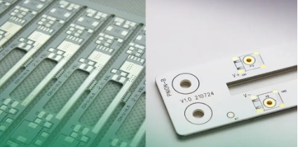
  In the realm of electronics, the choice of printed circuit board (PCB) material plays a pivotal role in determining the functionality, performance, and longevity of electronic devices. Two prominent contenders in this domain are aluminum-based PCBs and ceramic-based PCBs, each with its distinct advantages and specialized applications. Let’s delve deeper into the characteristics, pros, and cons of aluminum-based PCB vs ceramic-based PCB to aid in your decision-making process.  Aluminum-based PCBsAluminum-based PCBs, also recognized as metal core PCBs (MCPCBs), boast a core constructed from an aluminum alloy. These boards have garnered attention for their exceptional thermal conductivity and find extensive usage in applications that demand efficient heat dissipation.  Aluminum-based PCBs  Advantages of Aluminum-based PCBs  Thermal Conductivity: The standout feature of Aluminum-based PCBs is their remarkable thermal conductivity. This property makes them a preferred choice in applications where heat dissipation is critical, such as LED lighting systems, power converters, and automotive electronics. The ability to efficiently transfer heat away from sensitive components ensures enhanced reliability and longevity of the devices.  Cost-Efficiency: Aluminum-based PCBs often present a more budget-friendly option compared to certain high-performance materials. This cost-effectiveness makes them attractive for projects where optimizing expenses without compromising quality is a priority.  Lightweight Nature: Despite their robust construction, Aluminum-based PCBs maintain a relatively lightweight profile. This attribute proves advantageous in applications where weight considerations are pivotal, such as portable electronic devices or aerospace applications.  Manufacturing Simplicity: The manufacturing process for Aluminum-based PCBs is often simpler and more straightforward compared to some other materials, leading to reduced production time and costs.  However, these PCBs do come with their set of limitations, which might impact their suitability for specific applications.  Limitations of Aluminum-based PCBs  Electrical Insulation Requirements: Aluminum-based PCBs necessitate an insulating layer between the circuit and the metal base to prevent short circuits. This requirement adds complexity to the manufacturing process and design considerations, potentially increasing production costs.  Mechanical Strength: While durable, Aluminum-based PCBs might not offer the same level of mechanical strength as Ceramic-based PCBs. This factor could limit their use in applications exposed to harsh physical environments or substantial mechanical stress.  Ceramic-based PCBsCeramic-based PCBs, typically crafted from materials like aluminum oxide or aluminum nitride, have gained prominence owing to their outstanding electrical insulation properties and reliability in diverse applications.  Ceramic-based PCBs  Advantages of Ceramic-based PCBs  Superior Electrical Insulation: The hallmark of Ceramic-based PCBs lies in their superior electrical insulation capabilities. These boards excel in preventing signal interference and short circuits, making them ideal for high-voltage applications where maintaining signal integrity is crucial.  Enhanced Mechanical Strength: Ceramic-based PCBs exhibit greater mechanical strength compared to their Aluminum-based counterparts. This characteristic makes them well-suited for deployment in rugged environments or applications where resistance to mechanical stress is imperative.  High-Frequency Applications: With low dielectric loss and excellent signal integrity properties, Ceramic-based PCBs are highly sought after for high-frequency circuits and radio frequency (RF) applications.  Chemical Resistance: Ceramics demonstrate remarkable resistance to chemicals and corrosion, making Ceramic-based PCBs suitable for applications exposed to harsh and corrosive environments, such as in aerospace or industrial settings.  However, these boards also come with certain limitations that might influence their suitability for specific projects.  Limitations of Ceramic-based PCBs  Cost Considerations: Ceramic-based PCBs typically entail higher manufacturing costs due to the expense of materials and the complexity involved in their production. This factor might limit their feasibility for projects with stringent budget constraints.  Brittleness: Despite their mechanical strength, ceramics can be inherently brittle. Careful handling is required during production, assembly, and installation to prevent breakage, which can add to the overall project timeline and costs.  ConclusionThe choice between Aluminum-based and Ceramic-based PCBs hinges on a comprehensive evaluation of your project’s requirements, budget considerations, and the specific environmental conditions the electronic device will encounter.  For applications where thermal management and cost-effectiveness are paramount, Aluminum-based PCBs might prove more suitable. Conversely, if superior electrical insulation, mechanical robustness, and reliability in harsh conditions are essential, Ceramic-based PCBs could be the preferred option.  Ultimately, consulting with experienced PCB manufacturers or engineers remains pivotal in making an informed decision aligned with the unique demands of your electronic project.
Key word:
Release time:2023-12-15 13:26 reading:1777 Continue reading>>
What are the different types of electronics components packages?
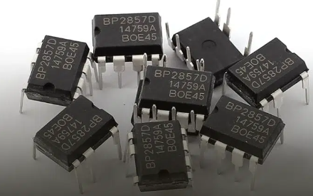
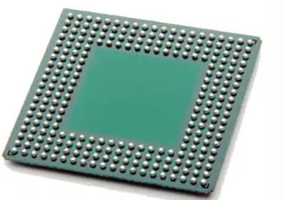
  In the realm of electronics, various packaging technologies cater to the diverse needs of components, ensuring functionality, compactness, and performance. These packaging methods are crucial in determining a component’s size, compatibility, and usage in different applications. Here, we delve into some of the most prevalent component packaging technologies shaping the electronic landscape:  1. Through-Hole Technology (THT)Through-Hole Technology (THT): DIP (Dual In-line Package), SIP (Single In-line Package), TO (Transistor Outline), etc.  Through-Hole Technology (THT) is a method used to mount and connect electronic components to a printed circuit board (PCB). In THT, leads (metal wires) extend from the electronic component and are inserted into pre-drilled holes on the PCB. Once inserted, the leads are soldered to pads on the opposite side of the board, forming a secure electrical and mechanical connection.  Components suitable for THT include resistors, capacitors, diodes, and integrated circuit sockets, among others. THT was one of the primary assembly methods for electronic components before the rise of Surface Mount Technology (SMT), which introduced smaller and more densely packed components suitable for automated assembly.  2. Surface Mount Technology (SMT)Surface Mount Technology (SMT): SOIC (Small Outline Integrated Circuit), QFP (Quad Flat Package), LGA (Land Grid Array), BGA (Ball Grid Array), etc.  Surface Mount Technology (SMT) is a method used in electronic assembly to mount and solder components directly onto the surface of a printed circuit board (PCB). In contrast to Through-Hole Technology (THT), which involves inserting component leads through holes in the PCB, SMT components have small metallic contacts or leads that sit directly on the board’s surface. SMT components are generally smaller and more compact than their through-hole counterparts, allowing for higher component densities and smaller PCB designs.  SMT components include resistors, capacitors, integrated circuits (ICs), diodes, and other semiconductor devices. The process involves soldering the components to the PCB’s surface using reflow soldering, where solder paste is applied to the board, and then the components are placed on the paste. The entire assembly is heated, causing the solder to melt and create a secure connection between the component leads and the PCB pads.  Surface Mount Technology has become the dominant method in modern electronics manufacturing due to its efficiency, miniaturization capabilities, and suitability for automated assembly processes.  3. Ball Grid Array (BGA)  Ball Grid Array (BGA): μBGA (Micro Ball Grid Array), CCGA (Ceramic Column Grid Array), PBGA (Plastic Ball Grid Array), etc.  Ball Grid Array (BGA) is a type of surface mount packaging used for integrated circuits (ICs) and other semiconductor devices. It’s characterized by an array of solder balls arranged in a grid formation on the underside of the component. These solder balls serve as the connection points to the PCB.  However, working with BGAs requires specialized equipment and techniques for both assembly and rework due to the complexity of soldering the numerous small solder balls. Nonetheless, they are widely used in various applications, especially in high-performance computing, gaming consoles, networking hardware, and consumer electronics, where space and performance are critical considerations.  4. Chip Scale Packaging (CSP)  Chip Scale Packaging (CSP): mCSP (micro Chip Scale Package), WLP (Wafer-Level Package), FC-CSP (Flip Chip Chip Scale Package), etc.  Chip Scale Packaging (CSP) refers to a packaging technology for integrated circuits (ICs) where the package size closely matches the dimensions of the silicon die or chip itself. In essence, CSPs aim to minimize the footprint of the package while providing the necessary protection and connections for the chip.  CSPs are commonly used in portable electronic devices such as smartphones, tablets, wearables, and other miniaturized gadgets. Their small form factor and efficient use of space make them ideal for applications demanding high-performance chips in constrained areas.  5. Quad Flat Packages (QFP)  Quad Flat Packages (QFP): TQFP (Thin Quad Flat Package), PQFP (Plastic Quad Flat Package), LQFP (Low-profile Quad Flat Package), etc.  Quad Flat Packages (QFP) are a type of surface mount integrated circuit package characterized by a flat body and leads extending from all four sides of the component. The leads are arranged in a grid pattern, allowing for easy soldering to the printed circuit board (PCB).  QFPs were a popular choice for integrating moderate-to-high pin counts in a compact form factor before more miniaturized packages, such as Ball Grid Arrays (BGAs) and Chip Scale Packages (CSPs), gained prominence in the electronics industry.  6. Plastic Leaded Chip Carrier (PLCC)  Plastic Leaded Chip Carrier (PLCC): PQFP (Plastic Quad Flat Package), LQFP (Low-profile Quad Flat Package), etc.  A Plastic Leaded Chip Carrier (PLCC) is a type of integrated circuit (IC) package used for surface-mounted devices. It’s a square or rectangular package made of plastic with metal leads extending from the sides. PLCC packages typically contain a semiconductor chip and have leads or pins on all four sides, which are used for connection to a circuit board.  PLCCs have largely been replaced by smaller and more efficient packages like quad flat no-leads (QFN) and ball grid arrays (BGAs) in many modern electronic devices due to their higher pin density, smaller footprint, and improved electrical performance.  7. Transistor Outline (TO) Packages  Transistor Outline (TO) Packages: TO-92, TO-220, TO-263, TO-220AB, etc.  Transistor Outline (TO) packages are a standardized type of packaging used for discrete semiconductor components like transistors and some integrated circuits. These packages are designed to provide a standardized form factor for easy handling, mounting, and heat dissipation.  The TO packages are convenient for manual or automated assembly onto circuit boards, and their standardized dimensions make them easily interchangeable in various electronic designs. However, due to advancements in technology, smaller and more efficient packages like surface-mount devices (SMDs) are becoming more prevalent in modern electronic designs, reducing the use of TO packages in some applications.  8. Dual Flat No-Lead (DFN) Packages  Dual Flat No-Lead (DFN) Packages: WDFN (Thin Dual Flat No-Lead), SON (Small Outline No-Lead), QFN (Quad Flat No-Lead), etc.  Dual Flat No-Lead (DFN) packages are a type of surface-mount semiconductor package used for integrated circuits (ICs), such as microcontrollers, integrated power devices, and sensors. The DFN package is characterized by its small size, low profile, and absence of leads or pins extending from the package sides.  DFN packages have a flat bottom with exposed metal pads arranged in a grid pattern. The electrical connections are made by soldering these pads directly onto corresponding pads on the surface of a printed circuit board (PCB). The absence of leads makes DFN packages suitable for high-density mounting, as they occupy less space and offer improved electrical performance due to shorter interconnection paths.  DFN packages are popular in modern electronic devices where miniaturization and efficient use of space are crucial design considerations. Their compact size, good thermal performance, and ability to accommodate higher pin counts make them favored choices in many consumer electronics, telecommunications, and portable devices.  9. Small Outline Package (SOP)  Small Outline Package (SOP): TSOP (Thin Small Outline Package), SSOP (Shrink Small Outline Package), HSOP (Heatsink Small Outline Package), etc.  The Small Outline Package (SOP) is a type of surface-mount technology used for integrated circuits. SOP packages are characterized by their rectangular shape with gull-wing or “J”-bend leads extending from the sides.  These packages come in different variants, such as SOP, SOP-8, SOP-16, etc., indicating the number of leads (pins) present on the package. For instance, SOP-8 has 8 leads, while SOP-16 has 16 leads.  SOP packages were popular in the 1980s and 1990s and remain in use for various applications, including memory chips, microcontrollers, and other ICs. They were widely adopted due to their ease of handling, small size, and compatibility with automated assembly processes.  The gull-wing leads of SOP packages make them suitable for mounting onto the surface of a printed circuit board (PCB), allowing for more efficient use of board space and facilitating high-density mounting. The leads are usually spaced in a standardized pattern to ensure compatibility and ease of design across different manufacturers.  10. Dual In-Line Package (DIP)  Dual In-Line Package (DIP): PDIP (Plastic Dual In-line Package), CDIP (Ceramic Dual In-line Package), etc.  The Dual In-Line Package (DIP) is a type of electronic component package used primarily for integrated circuits (ICs) and other similar semiconductor devices. DIPs were widely used in the earlier days of electronics and computing but have become less common with advancements in surface-mount technology.  DIPs were prevalent in early computers, microcontrollers, memory chips, and other integrated circuits. However, as technology progressed, smaller and more efficient surface-mount packages like quad flat packages (QFP), small outline packages (SOP), and ball grid arrays (BGAs) gained popularity due to their smaller footprint, higher pin density, and better electrical performance.  11. Chip on Board (COB)  Chip on Board (COB): The semiconductor chip is mounted directly onto the PCB.  Chip on Board (COB) refers to a packaging technology in which semiconductor chips are mounted directly onto a substrate or circuit board and then covered with a protective layer of epoxy resin or other encapsulation materials. Instead of using traditional individual packages for each chip, COB involves placing bare semiconductor chips directly onto the substrate and connecting them through wire bonding or flip-chip bonding techniques.  COB technology finds applications in various electronic devices, including LED lighting, RFID tags, sensor modules, and certain types of microcontrollers. Its advantages in size, cost, and durability make it suitable for specific applications where space constraints and reliability are critical factors.  12. Metal Can Packages  Metal Can Packages: TO-CAN, FET CAN, etc.  Metal can packages refer to a type of packaging used for semiconductor devices, particularly in the early days of integrated circuits and discrete electronic components. These packages are made of metal and are designed to protect the semiconductor chip or component from environmental factors and provide mechanical stability.  Metal can packages were widely used in the past for diodes, transistors, operational amplifiers, and other electronic components. However, with advancements in semiconductor packaging technology, newer packaging formats like surface-mount packages (SMDs), plastic packages, and ceramic packages have become more prevalent due to their smaller size, lighter weight, and better thermal performance.  Despite their declining use in modern electronics, metal can packages are still employed in specialized applications where their specific properties, such as hermetic sealing or high-reliability requirements, are crucial, such as in certain military, aerospace, or high-reliability industrial applications.  13. Flip Chip  Flip Chip: The die is flipped onto the substrate and bonded without packaging.  Flip chip is an advanced packaging technique used in semiconductor manufacturing where the active surface of a microchip is inverted and directly connected to the substrate or carrier using tiny solder bumps or metal bumps. Instead of traditional wire bonding, where wires connect the chip to the substrate, flip chip technology directly attaches the active side of the chip to the carrier.  Flip chip technology is widely used in various applications, including microprocessors, memory chips, graphic processors, and high-performance integrated circuits found in computers, smartphones, networking devices, and other electronic devices. Its advantages in terms of performance, size, and reliability have made it a preferred packaging method in the semiconductor industry for many high-performance applications.  14. Wafer-Level Chip Scale Package (WLCSP)  Wafer-Level Chip Scale Package (WLCSP): Direct chip attachment on the wafer level.  Wafer-Level Chip Scale Package (WLCSP) is an advanced semiconductor packaging technology used to create extremely compact and miniaturized packages for integrated circuits (ICs). WLCSP is designed to minimize the package footprint, making it almost the same size as the actual semiconductor die, resulting in an ultra-small and thin package.  WLCSP technology involves the packaging process occurring directly on the wafer during the semiconductor manufacturing process. The individual ICs are packaged at the wafer level before they are separated into individual chips (dies). This approach reduces manufacturing steps and cost compared to traditional packaging methods.  WLCSPs are commonly used in various electronic devices where space savings, high performance, and miniaturization are essential, such as in mobile devices (smartphones, wearables), medical devices, and portable electronics.  15. Ceramic Packages  Ceramic Packages: Cerdip (Ceramic Dual In-line Package), CQFP (Ceramic Quad Flat Package), etc.  Ceramic packages are a type of semiconductor packaging made primarily from ceramic materials. These packages are used to encapsulate and protect integrated circuits (ICs), transistors, and other semiconductor devices.  Ceramic packages have been widely used in applications where high reliability, ruggedness, and thermal management are critical, such as in aerospace, automotive electronics, military applications, and certain industrial settings.  However, ceramic packaging tends to be more expensive compared to plastic or other materials, which has led to the development of alternative packaging technologies for consumer electronics. Nevertheless, for applications requiring superior thermal performance, reliability, and resilience to extreme conditions, ceramic packages remain a preferred choice.  16. Ceramic Ball Grid Array (CBGA)  Ceramic Ball Grid Array (CBGA): Ceramic package with a grid array of solder balls.  A Ceramic Ball Grid Array (CBGA) is a type of packaging used for integrated circuits (ICs) and semiconductor devices. It’s a variation of the ball grid array (BGA) packaging, where the package substrate is made of ceramic material instead of organic material (like fiberglass-reinforced epoxy resin).  CBGA packages are commonly used in applications that demand high reliability, ruggedness, and superior thermal management. These include aerospace, military, automotive, and certain industrial applications where extreme temperatures, mechanical stress, or harsh environments are encountered.  However, CBGA packages tend to be more expensive to manufacture compared to their organic substrate counterparts (like plastic BGAs), which has led to their more limited use in certain consumer electronics applications. Nevertheless, their exceptional thermal performance and reliability make them a preferred choice for specific high-end applications.  17. Hermetic Sealed Packages  Hermetic Sealed Packages: Complete seal for protection against environmental factors.  Hermetic sealed packages refer to electronic packaging that provides an airtight and moisture-proof enclosure for semiconductor devices, integrated circuits (ICs), sensors, or other sensitive electronic components. The term “hermetic” implies a complete seal that prevents the ingress of gases or moisture into the package.  Hermetic sealing ensures the long-term integrity and reliability of sensitive electronic components, especially in environments where exposure to moisture, gases, or contaminants could compromise their functionality. This level of protection is essential for maintaining the performance and longevity of electronic devices in demanding and critical applications.  18. Molded Packages  Molded Packages: Enclosed in a protective mold to shield against moisture and contaminants.  Molded packages, in the context of semiconductor manufacturing, refer to packaging technology where semiconductor devices or integrated circuits (ICs) are encapsulated within a molded plastic or resin material. This process involves molding the semiconductor chip and connecting wires within a protective casing made of plastic or resin.  These packages are not limited to a single type but encompass various packaging styles, such as Dual In-Line Packages (DIPs), Small Outline Packages (SOPs), Quad Flat Packages (QFPs), and many others. Molded plastic or resin packaging has been widely used due to its versatility, cost-effectiveness, and ability to meet the needs of various electronic applications.  19. Hybrid Packages  Hybrid Packages: Combines different packaging types into a single component.  Hybrid packages refer to semiconductor packaging that combines multiple semiconductor or electronic components in a single package, typically integrating different technologies or types of components onto a common substrate. These packages are called “hybrid” because they merge diverse technologies or functionalities within one enclosure.  The manufacturing of hybrid packages involves assembling different components onto a common substrate, which can be ceramic, organic, or other materials suitable for accommodating the diverse technologies being integrated. Assembly methods may involve wire bonding, die attach, flip chip bonding, or other advanced packaging techniques.  Hybrid packages offer a versatile solution for combining different electronic components to achieve desired functionalities, making them valuable in various industries where specific and specialized applications demand tailored solutions.  20. System-in-Package (SiP)  System-in-Package (SiP): Integrates multiple chips or devices into a single package.  System-in-Package (SiP) is an advanced packaging technology that integrates multiple chips, dies, or diverse components into a single package, forming a complete functional system. It differs from traditional multi-chip modules or single-chip ICs by combining various functionalities or entire subsystems into a compact and integrated package.  SiP technology finds applications in various fields, including mobile devices, Internet of Things (IoT) devices, wearables, telecommunications, automotive electronics, and more. Its ability to combine multiple functions or subsystems into a single package makes SiP an efficient and space-saving solution for complex electronic systems.  The manufacturing process for SiP involves assembling and interconnecting various chips or components onto a common substrate using advanced packaging techniques. Design considerations include thermal management, signal integrity, power distribution, and overall system optimization to ensure optimal performance of the integrated system.  Each of these packaging technologies serves specific purposes, balancing factors like size, performance, thermal management, and environmental protection for various electronic components and devices.  These packaging technologies, with their unique designs and functionalities, enable the creation of intricate electronic systems across diverse industries. Their evolution continues to meet the demands of miniaturization, performance enhancement, and innovation in modern electronics.
Key word:
Release time:2023-12-14 13:40 reading:1674 Continue reading>>
A World’s First: Murata Enables Better Wi-Fi 6E and Wi-Fi 7 Antenna Design with Cutting-Edge Parasitic Element Coupling Device
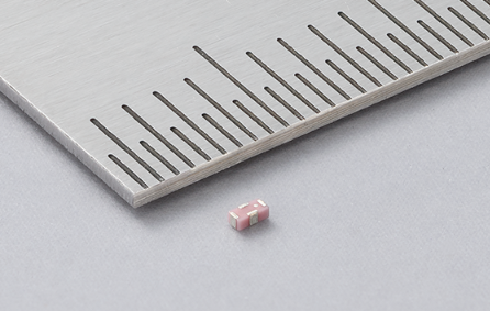
  Murata has announced its new Parasitic Element Coupling Device. This state-of-the-art solution improves antenna efficiency by magnetically coupling the parasitic element with the antenna and is the world's first solution designed for Wi-Fi 6E and Wi-Fi 7 products. For designers of smartphones, tablets, network routers, game consoles, and other compact electronics, it enables them to build more efficient antennas – a key requirement for many modern space-constrained devices.  To develop products conforming to Wi-Fi 6E and Wi-Fi 7 standards, which utilize high-speed wireless communication, multiple high-performance antennas must be installed in electronic devices to improve communication speed and quality.  However, as the dimensions of heatsinks and batteries expand, as processors become more advanced, the available space for mounting antennas tends to decrease.  Consequently, there is a need for smaller antennas. But there is a technical limitation, in that the efficiency of wide-band antennas decreases when they are miniaturized. Therefore, designers need a solution that achieves both miniaturization and high performance.  Murata’s solution is a parasitic element coupling device, made with its multilayer technology as a four-terminal surface-mount component of just 1.0 x 0.5 x 0.35mm.  Murata’s parasitic element coupling device connects the feeding antenna* to its parasitic elements more effectively than is possible through free space. It acts as a tiny coupling device whose compact size enables strong coupling performance without the use of magnetic materials, which would be inappropriate at the targeted operating frequencies. One side of the coupling device is connected, at very low insertion loss, between a device’s RF circuitry and its main antenna. The other side is connected between the ground and the parasitic element. The resultant, more direct coupling enables the resonance characteristics of the parasitic element to be added to those of the feeding antenna. As a result, it enables more efficient operation across a broader frequency range or on multiple discrete bands.  The device helps to combat that when an antenna is made smaller, the coupling between it and the parasitic elements is reduced, while the coupling between the parasitic elements and the ground is increased. By sustaining the coupling between the feeding antenna and parasitic element, parasitic element coupling device enables designers to use miniaturized antenna design methods without impacting the communication band of efficiency.  The feeding antenna can cause an impedance mismatch when used over a wide band, leading to a degradation in wireless performance. In addition, when an antenna with a mismatched impedance is connected to a communication circuit using a long cable, the long cable can promote the impedance mismatch, causing larger insertion loss than expected and significantly reducing wireless communication performance. By using the device, you can improve antenna matching and reduce performance degradation in wireless communications even when using long cables.
Key word:
Release time:2023-12-13 14:15 reading:2310 Continue reading>>
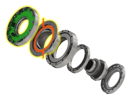
Nidec Drive Technology Develops Smart-FLEXWAVE, the World’s First Precision Reducer with Multiple Built-in Sensors
Key word:
Release time:2023-12-12 14:24 reading:2116 Continue reading>>
Renesas Programmable Motor Driver ICs Are First to Enable Full Torque at Zero Speed for Sensorless Brushless DC Motors
  TOKYO, Japan ― Renesas Electronics Corporation (TSE:6723), a premier supplier of advanced semiconductor solutions, today introduced a family of motor driver ICs for brushless DC (BLDC) motor applications. The devices implement Renesas’ new, patent-pending technologies that enable full torque at zero speed from motors without sensors, an industry first. The new motor driver ICs enable Renesas customers to design sensorless BLDC motor systems with higher horsepower and speed at a given torque. They also improve power consumption and reliability, while reducing cost and board space by lowering the number of components designers need to use.  Renesas is introducing three new motor driver ICs with the new technology. The RAA306012 65V, 3-phase Smart Driver is a standalone device that can be paired with a variety of MCUs from Renesas or from other sources. The RAJ306101 integrates a Renesas RX13T 32-bit MCU with the RAA306012 in a single package, reducing board space and improving cost and reliability. The RAJ306102 integrates a 16-bit Renesas RL78/G1F MCU with the RAA306012, providing similar integration benefits.  The ability to enable full torque at zero speed without sensors is made possible by two Renesas innovations. Enhanced Inductive Sensing (EIS) offers stable position detection when the motor is completely stopped. When the motor is operating at extremely low speed, Motor Rotor position Identification (MRI) is used. At higher speeds, the new motor driver ICs use conventional methods. Both of the new EIS and MRI algorithms include patent-pending technology developed by Renesas.  “The advantages of sensorless design are numerous, including cost, space, power and reliability,” said Davin Lee, Vice President of the Advanced Analog Division at Renesas. “Our customers can now enjoy these benefits for systems that require full torque at zero speed. This industry first is a great example of Renesas combining our technical prowess with deep application knowledge to deliver a solution that meets a clear market need.”  “We are eager to implement sensorless technology into new products where we previously had to include sensors,” said Peter Korošec, President and CEO at Domel Inc, a global supplier of electric motors, vacuum motors, blowers, and components. “This breakthrough from Renesas will enable us to provide new products for our customers with the best available size, cost and reliability.”  Key Features of the Renesas New Motor Driver ICs  High integration including drivers, power management and current sensing  Adaptive and adjustable dead time improves efficiency  Charge pump maintains steady gate drive voltage at programmed settings  Programmable gate drive voltage enables driving of N MOSFETs and GaN FETs  Rich sensing blocks allow for better accuracy and wide-speed RPM drive  16 programmable slew rate settings minimize electromagnetic emissions  Supports all types of motor control algorithms such as Trapezoidal, Sinusoidal, and FOC  Extensive protection functions improve system safety  Winning Combinations  Renesas has combined the new motor driver ICs with complementary components from its portfolio to offer a wide array of Winning Combinations, including Cordless Vacuum Cleaner and 20V Cordless Leaf Blower. These Winning Combinations are technically vetted system architectures from mutually compatible devices that work together seamlessly to bring an optimized, low-risk design for faster time to market. Renesas offers more than 400 Winning Combinations with a wide range of products from the Renesas portfolio to enable customers to speed up the design process and bring their products to market more quickly. They can be found at renesas.com/win.  Availability  The RAA306012, RAJ306101, and RAJ306102 are available today. The RAA306012 is available in a 7mm x 7mm 48-pin QFN package. The RAJ306101 and RAJ306102 are offered in 8 x 8 mm 56-pin and 64-pin QFNs, respectively. Renesas is also offering evaluation kits for each of the new devices.
Key word:
Release time:2023-12-08 17:02 reading:2171 Continue reading>>
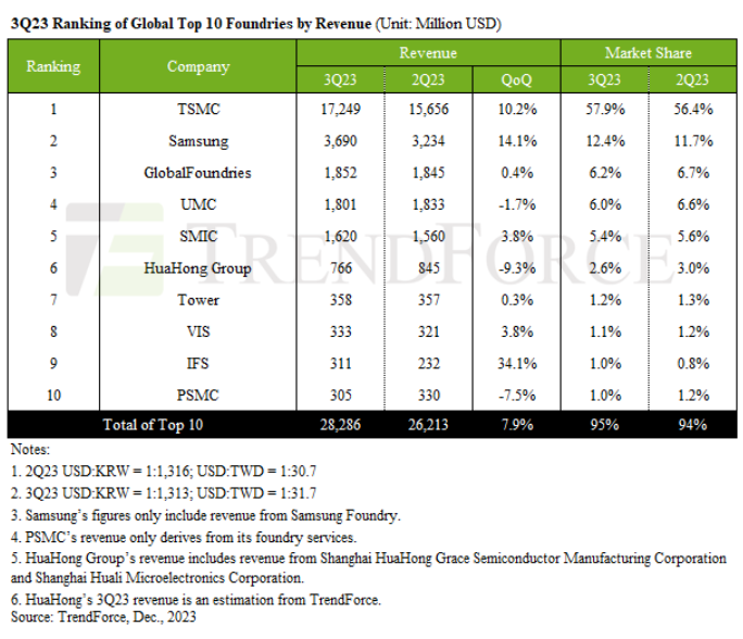
Top 10 Foundries Experience 7.9% QoQ Growth in 3Q23, with a Continued Upward Trend Predicted for Q4, Says TrendForce
  TrendForce’s research indicates a dynamic third quarter for the global foundry industry, marked by an uptick in urgent orders for smartphone and notebook components. This surge was fueled by healthy inventory levels and the release of new iPhone and Android devices in 2H23. Despite persisting inflation risks and market uncertainties, these orders were predominantly executed as rush orders. Additionally, TSMC and Samsung’s high-cost 3nm manufacturing process had a positive impact on revenues, driving the 3Q23 value of the top ten global foundries to approximately US$28.29 billion—a 7.9% QoQ increase.  Looking ahead to 4Q23, the anticipation of year-end festive demand is expected to sustain the inflow of urgent orders for smartphones and laptops, particularly for smartphone components. Although the end-user market is yet to fully recover, pre-sales season stockpiling for Chinese Android smartphones appears to be slightly better than expected, with demand for mid-to-low range 5G and 4G phone APs and continued interest in new iPhone models. This scenario suggests a continued upward trend for the top ten global foundries in Q4, potentially exceeding the growth rate seen in Q3.  TSMC’s 3nm process contributes substantially to revenue as it claims 58% market share in Q3  TSMC’s revenue grew by 10.2%—reaching US$17.25 billion—supported by strong demand in the PC sector and for smartphone components, including new iPhones and Android devices, as well as urgent orders for restocking mid-to-low end 5G and 4G inventories. The 3nm process alone contributed 6% to TSMC’s Q3 revenue, with advanced processes (≤7nm) accounting for nearly 60% of its total revenue.  Samsung Foundry also experienced robust growth, with its revenue reaching US$3.69 billion in Q3, a 14.1% QoQ increase. This was driven by orders for Qualcomm’s mid-to-low range 5G AP SoC, 5G modems, and mature 28 nm OLED DDI processes.  GlobalFoundries maintained a stable performance in Q3, with its revenue approximating US$1.85 billion, similar to the previous quarter. The company's revenue was predominantly supported by the home and industrial Internet of Things (IoT) sectors, which accounted for approximately 20% of its total revenue. Furthermore, a significant portion of this revenue boost was due to orders from the US aerospace and defense sectors.  UMC benefited from the support of urgent orders, which largely offset adjustments in automotive orders. Despite a slight decline in overall wafer shipments, UMC’s revenue experienced a minor quarterly decrease of 1.7%, amounting to approximately US$1.8 billion. Notably, the revenue from its 28/22 nm products saw a near 10% increase, representing 32% of UMC’s total revenue.  SMIC benefited from seasonal consumer product demands, especially urgent smartphone-related orders, leading to a 3.8% revenue increase fo US$1.62 billion in Q3. However, due to the diversification of the supply chain and the relocation of American customers outside China, the revenue share from American clients decreased to 12.9%. Conversely, revenue from Chinese clients increased to 84% due to the government’s localization initiatives and urgent orders for smartphone components.  IFS makes debut in rankings with highest revenue growth in Q3  Notable changes in the rankings from sixth to tenth position include VIS and IFS, with the latter entering the global top for the first time since Intel’s financial restructuring. VIS’ Q3 revenue increased by 3.8% to US$333 million—surpassing PSMC to take the eighth position—thanks to a recovery in LDDI and panel-related PMIC orders and prebuilt wafer shipments. IFS benefited from seasonal laptop orders in 2H23 and contributions from its advanced high-priced processes, recording a 34.1% increase in revenue to approximately US$311 million.  Other companies like HuaHong Group saw a 9.3% decrease in Q3 revenue to about US$766 million. HHGrace maintained steady wafer shipment levels from the previous quarter, but a roughly 10% decrease in ASP led to a decline in revenue. Tower Semiconductor saw stable demand in the smartphone, automotive, and industrial sectors, maintaining revenue at around US$358 million in Q3. PSMC witnessed a 7.5% drop in revenue to US$305 million, with PMIC and Power Discrete revenues declining nearly 10% and 20%, respectively, impacting overall performance.
Key word:
Release time:2023-12-07 15:58 reading:1996 Continue reading>>
What are the different types of photocoupler?  What is the function of a photocoupler?
  What is the definition of a photocoupler?A photocoupler, also known as an optocoupler, is an electronic component used to transfer electrical signals between two isolated circuits using light. It comprises a light-emitting diode (LED) that emits light when current passes through it and a photosensitive semiconductor device (like a photodiode or phototransistor) that detects this light and converts it back into an electrical signal.  The key purpose of a photocoupler is to provide electrical isolation between two parts of an electronic system. This isolation prevents high voltages, noise, or potential differences in one circuit from affecting or damaging another circuit. It’s commonly used in applications where safety, signal integrity, and noise reduction between different parts of a circuit are critical. For instance, they’re used in power supplies, communication systems, and in controlling high-voltage devices from low-voltage control circuits.  What are the different types of photocoupler?  Photocouplers, or optocouplers, come in various types, each designed for specific applications and operating conditions. Here are some common types:  Photodiode Couplers: These use a photodiode to detect light emitted by an LED. They are primarily used for simple applications requiring basic isolation.  Phototransistor Couplers: Instead of a photodiode, these use a phototransistor to detect light. They provide higher sensitivity and better amplification, making them suitable for applications where higher isolation or signal amplification is required.  Photovoltaic Couplers: These optocouplers generate voltage directly when exposed to light, eliminating the need for a separate power supply. They offer fast response times and are used in high-speed applications.  Solid-State Relays (SSRs): Combining optocouplers with a semiconductor switch, SSRs use an optocoupler to isolate the control and load circuits in relay-based applications. They offer advantages like fast switching speed and long lifespan compared to mechanical relays.  High-Speed Optocouplers: Specifically designed for high-speed data transmission, these optocouplers offer increased bandwidth and faster response times, suitable for applications like fiber optic communication systems and data transmission.  Gate Drive Optocouplers: These are used in driving power semiconductor devices like MOSFETs or IGBTs, providing electrical isolation between the control and power circuits. They ensure accurate switching and prevent electrical noise from affecting the control circuit.  Each type of photocoupler has its advantages and is chosen based on factors like speed, isolation requirements, power consumption, and the specific application’s needs.  What is the function of a photocoupler?A photocoupler, also known as an optocoupler, serves the essential function of providing electrical isolation between two separate circuits while allowing information or signals to pass between them via light. It consists of an LED (Light Emitting Diode) that emits light and a photosensitive component, like a photodiode or a phototransistor, that detects this light.  The primary functions of a photocoupler include:  Electrical Isolation: It prevents direct electrical contact between two circuits that might operate at different potentials or have different ground references. This isolation protects sensitive components from voltage surges, noise, or faults in one circuit from affecting the other.  Signal Transfer: The light emitted by the LED in one section is detected by the photosensitive component in another section. This enables the transfer of signals, data, or control commands between isolated circuits without the need for direct electrical connections.  Noise Suppression: Photocouplers can effectively suppress electromagnetic interference (EMI) or electrical noise that could otherwise disrupt signals passing between circuits.  Voltage Level Shifting: In some cases, photocouplers can help in shifting voltage levels between different parts of a circuit, allowing compatibility between systems with varying voltage requirements.  Switching and Control: They are also used to control power devices such as transistors or relays by isolating the control circuit from the high-power or high-voltage circuit. This ensures safety and prevents damage to sensitive control components.  Overall, photocouplers play a crucial role in ensuring safety, reliability, and proper operation in various electronic systems by enabling communication and control between different sections while keeping them electrically isolated.  What’s the application of photocoupler?Photocouplers, or optocouplers, find applications across various industries and electronic devices due to their ability to provide electrical isolation while transmitting signals optically. Some common applications include:  Switching Power Supplies: Used for feedback control, error detection, and voltage regulation in power supplies, ensuring safety and stability by isolating high-voltage sections from low-voltage control circuits.  Industrial Control Systems: Employed in motor drives, PLCs (Programmable Logic Controllers), and robotics for signal isolation, noise reduction, and ensuring safety in high-voltage environments.  Telecommunication Equipment: Utilized in modems, routers, and other networking devices to isolate data lines, reduce noise, and protect against voltage surges.  Medical Devices: Found in various medical equipment like patient monitoring systems, infusion pumps, and defibrillators to isolate sensitive electronic components from potential electrical hazards.  Automotive Electronics: Used in automotive systems for isolating control signals in electric vehicles, hybrid vehicles, engine control units, and safety systems to ensure proper operation and safety.  Audio Equipment: Applied in audio amplifiers, mixers, and other audio devices to reduce noise and prevent ground loop issues.  Isolated Data Communication: Employed in isolated USB interfaces, isolated RS-232, RS-485, or CAN bus interfaces for secure data transmission in noisy environments.  Isolated Gate Drivers: Used in controlling power switches like MOSFETs or IGBTs in motor control, inverters, and high-power applications where galvanic isolation is necessary.  Signal Isolation in Control Circuits: Applied in control systems for isolation between microcontrollers and sensors, or in feedback loops for accurate signal transmission without interference.  Isolated Sensing Circuits: Utilized in isolation amplifiers or sensor interfaces to isolate and amplify sensor signals accurately without ground loops or noise interference.  Photocouplers play a critical role in ensuring safety, noise reduction, and reliable signal transmission in numerous electronic systems across various industries where electrical isolation is essential.  How does a photocoupler work?A photocoupler, also known as an optocoupler, functions by transmitting signals between two isolated circuits using light. It typically consists of an LED (light-emitting diode) and a photodetector, both encased in a light-proof package.  Here’s how it generally works:  • LED Emission: When an electrical signal is applied to the LED inside the package, it emits light. This light is used to transmit signals across the isolation barrier.  • Photodetector Reception: The emitted light reaches the photodetector, which converts the light signal back into an electrical signal. This photodetector can be a phototransistor, photodiode, or other light-sensitive semiconductor devices.  • Isolation Barrier: The physical barrier between the LED and the photodetector provides electrical isolation, preventing direct electrical contact between the input and output circuits. This isolation protects sensitive components in one circuit from potential issues in the other.  • Signal Transmission: The input circuit controls the LED, while the output circuit detects the light emitted by the LED. Any changes in the input signal controlling the LED are replicated in the output as variations in the received light signal.  By converting electrical signals into light and then back into electrical signals, photocouplers facilitate signal transmission between circuits while ensuring electrical isolation. This isolation protects sensitive components from high voltages, noise, and potential damage, making them valuable in various applications where safety and signal integrity are crucial.  What is the difference between transformer and optocoupler?Transformers and optocouplers serve different purposes and operate on different principles despite sharing some similarities in their function to transfer signals.  Transformer:  Principle: Transformers work based on electromagnetic induction. They consist of two coils wound around a common core. An alternating current in the primary coil induces a magnetic field in the core, which, in turn, induces a current in the secondary coil.  Isolation: Transformers provide electrical isolation by transferring power or signals magnetically. They’re used for voltage conversion, impedance matching, and signal isolation.  Applications: They are commonly used in power supplies, signal amplification, and impedance matching.  Optocoupler:  Principle: Optocouplers, also known as photocouplers, function by transferring signals through light. They consist of an LED and a photodetector, providing electrical isolation by transmitting signals optically.  Isolation: The primary purpose is to provide electrical isolation between input and output circuits. They’re used to control or transmit signals across isolated circuits while preventing electrical connections between them.  Applications: Commonly used in digital communication, switching power supplies, motor control, and interfacing microcontrollers.  Key Differences:  Principle of Operation: Transformers work on the principle of electromagnetic induction, while optocouplers function through light transmission.  Signal Transfer Method: Transformers transfer signals through magnetic coupling, while optocouplers transfer signals using light (photons).  Isolation: While both devices offer electrical isolation, transformers isolate through magnetic fields, and optocouplers provide isolation via light transmission.  Applications: Transformers are typically used for voltage conversion, power transfer, and impedance matching. Optocouplers are used for signal transmission, noise isolation, and circuit protection.
Key word:
Release time:2023-12-07 15:53 reading:1560 Continue reading>>
ROHM Offers the Industry’s Largest* Library of LTspice® Models at Over 3,500 by Adding SiC and IGBTs
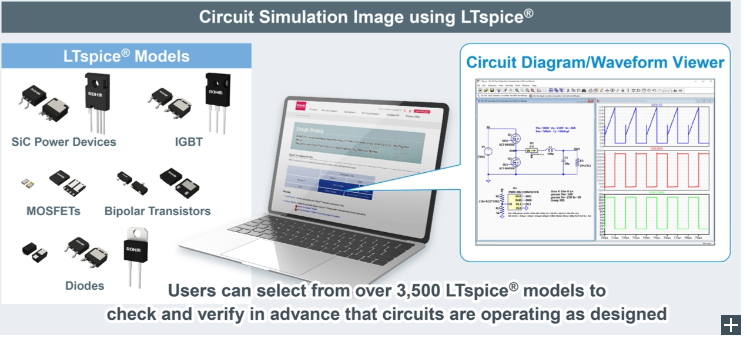
  ROHM has expanded the library of SPICE model lineup for LTspice® of its circuit simulator. LTspice® is also equipped with circuit diagram capture and waveform viewer functions that make it possible for designers to check and verify in advance whether the circuit operation has been achieved as designed. In addition to the existing lineup of bipolar transistors, diodes, and MOSFETs, ROHM has added SiC power devices and IGBTs that increases its number of LTspice® models to more than 3,500 for discretes (which can be downloaded from product pages). This brings the amount of coverage of LTspice® models on ROHM’s website to over 80% of all products - providing greater convenience to designers when using circuit simulators that incorporate discrete products, now including power devices.  In recent years, the increasing use of circuit simulation for circuit design has expanded the number of tools being utilized. Among these, LTspice® is an attractive option for a range of users, from students to even seasoned engineers at well-known companies. To support these and other users, ROHM has expanded its library of LTspice® models for discrete products.  Besides product pages, ROHM has added a Design Models page in October that allows simulation models to be downloaded directly. Documentation on how to add libraries and create symbols (schematic symbols) is also available to facilitate circuit design and simulation execution.  Going forward, ROHM will continue to contribute to solving circuit design issues by expanding the number of models compatible with various simulators while providing web tools such as ROHM Solution Simulator to meet growing customer needs.  TerminologySPICE Model  Data that expresses the operating characteristics of elements in mathematical equations for use in electronic circuit simulations. The SPICE model format may differ depending on the simulator (usually in the form of a text file).  Circuit Simulator  A software-based tool that makes it possible to design and verify electronic circuits without the need for actual electronic components.  MOSFET (Metal Oxide Semiconductor Field Effect Transistor)  The most commonly used structure in FETs.  IGBT (Insulated Gate Bipolar Transistor)  A power transistor that combines the high-speed switching characteristics of a MOSFET with the low conduction loss of a bipolar transistor.  ROHM Solution Simulator  A free electronic circuit simulation tool that runs on ROHM’s website. A wide variety of simulations are supported, from component selection and standalone device verification to system-level operational testing.
Key word:
Release time:2023-12-06 11:52 reading:1960 Continue reading>>
ROHM’s New High Power 120W Laser Diode for LiD<span style='color:red'>AR</span>: Increasing Measurement Range by Reducing Wavelength Temperature Dependence by 66%
  ROHM has developed a high-power laser diode - the RLD90QZW8. It is ideal for industrial equipment and consumer applications requiring distance measurement and spatial recognition.  In recent years, LiDAR is being increasingly adopted in a wide range of applications that require automation - including AGVs (Automated Guided Vehicles), robot vacuums, and autonomous vehicles - where it is necessary to accurately measure distance and recognize space. In this context, there is a need to improve the performance and output of laser diodes when used as light sources to increase detection distance and accuracy.  To meet this demand, ROHM established original patented technology to achieve a narrower emission width that contributes to longer range and higher accuracy in LiDAR applications. In 2019, ROHM released a 25W laser diode RLD90QZW5 followed by a 75W laser diode RLD90QZW3 in 2021. In response to the growing market demand for even higher output, ROHM developed a new 120W laser diode.  The RLD90QZW8 is a 120W infrared high output laser diode developed for LiDAR used in distance measurement and spatial recognition in 3D ToF systems. Original device development technology allows ROHM to reduce the temperature dependence of the laser wavelength by 66% over general products, to just ⊿11.6nm (Ave. 0.10nm/°C). This makes it possible to narrow the bandpass filter while extending the detection range of LiDAR. At the same time, a uniform light intensity of 97% is achieved over the industry's smallest class* of emission width of 270µm, representing a range of 264µm that contributes to higher resolution. Additional features that include high power-to-light conversion efficiency (PCE) enables efficient optical output that contributes to lower power consumption in LiDAR applications.  A variety of design support materials necessary for integrating and evaluating the new product is available free of charge on ROHM’s website that facilitate market introduction. In order to drive laser diodes with high nano-second order speed required for LiDAR applications, ROHM developed a reference design available now that combines ROHM’s 150V EcoGaN™ HEMT and gate drivers.  ROHM has also acquired certification under the IATF 16949 automotive quality management standard for both front-end and back-end processes at its manufacturing facilities. As a result, product development of laser diodes for automotive applications (AEC-Q102 compliant) is underway, with commercialization planned by the end of 2024.  Application ExamplesConsumer: Robot vacuums, Laser rangefinders  Industrial: AGVs (Automated Guided Vehicles), service robots, 3D monitoring systems (sensors for human/object detection)  and more...  Support PageA broad range of design data is available on ROHM’s website free of charge, including simulation (SPICE) models, board development data, and application notes on drive circuit design necessary for integration and evaluation that supports quick market introduction.  Reference DesignsReference designs for LiDAR incorporating these new products together with ROHM’s 150V EcoGaN™ and high-speed gate driver (BD2311NVX series) are now available on ROHM’s website.  Reference Design Part Nos.  ・REFLD002-1  (120W High Power Laser Diode [RLD90QZW8] built-in)  ・REFLD002-2  (75W High Power Laser Diode [RLD90QZW3] built-in)  EcoGaN™ is a trademark or registered trademark of ROHM Co., Ltd.  Online Sales InformationSales Launch Date: September 2023  Pricing: $30.0/unit (samples, excluding tax)  Online Distributors: DigiKey, Mouser and Farnell  The product will be offered at other online distributors as they become available.  Target Product: RLD90QZW8-00A  Online Distributors  TerminologyLiDAR  Short for Light Detection and Ranging, a type of application that uses ToF (Time of Flight) system (comprised of a light source and ToF or image sensor) to sense ambient conditions.  3D ToF System  An abbreviation for Time of Flight, a spatial measurement system which, as its name implies, measures the flight time of a light source. Refers to a system that uses ToF to perform 3D spatial recognition and distance measurement.  Bandpass Filter  A filter that allows only signals in a specific light wavelength band to pass through. In optical devices, a narrow bandpass filter range allows for efficient extraction of light close to the peak waveform. This minimizes the effects of disturbance light noise such as sunlight, enabling lower power consumption at the same distance or longer range at the same optical output.  IATF 16949  IATF is the short for International Automotive Task Force, a quality management standard for the automotive industry. Based on the international standard ISO 9001 with additional specific requirements, compliance with IATF 16949 enables automakers and suppliers to meet international quality standards.  AEC-Q102  AEC stands for Automotive Electronics Council, an organization (comprised of major automotive manufacturers and US electronic component makers) responsible for establishing reliability standards for automotive electronics. Q102 is a standard specifically intended for optical devices.
Key word:
Release time:2023-12-05 15:21 reading:1930 Continue reading>>
What is the difference between thick film and thin film circuit board?
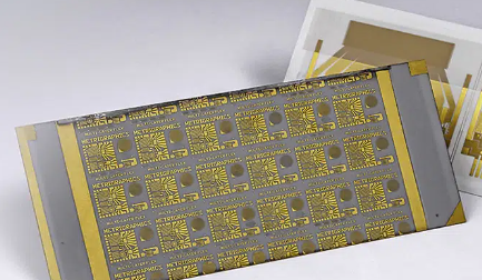
  Thin film circuit boards are specialized substrates used in electronic applications where precision, miniaturization, and high performance are crucial. They’re constructed by depositing thin layers of conductive, resistive, or insulating materials onto a substrate, typically made of ceramic or glass.  What is a thick film circuit board?A thick film circuit board refers to a type of printed circuit board (PCB) that utilizes thick film technology in its manufacturing process. In contrast to traditional thin film PCBs, which use thin layers of conductive material deposited on the board, thick film circuit boards involve the deposition of thicker layers of conductive and resistive materials on the board’s surface.  The manufacturing process involves screen printing a paste-like mixture of conductive materials, such as silver, gold, or palladium, along with glass or ceramic materials, onto the substrate. This thick film paste is then fired at high temperatures to fuse the materials onto the board, forming the conductive traces, resistors, and other circuit elements.Thick film circuit boards offer several advantages:  Cost-Effectiveness: The manufacturing process is generally less expensive compared to traditional thin film technologies.  Ease of Prototyping: Thick film technology allows for rapid prototyping and quick modifications to circuit designs.  Adaptability: They are suitable for hybrid circuits, combining both passive and active components on the same substrate.  Robustness: Thick film boards tend to be more durable and resistant to environmental factors like moisture and temperature variations.  These boards find applications in various industries, including automotive electronics, industrial controls, sensors, and certain medical devices where cost-effective and robust circuitry is required.  What is a thin film circuit board used for?Thin film circuit boards are primarily used in applications where high precision, high-frequency, and high-performance electronic circuits are necessary. These boards are manufactured by depositing thin layers of conductive materials, typically metals like gold, platinum, or alloys, onto a substrate using specialized deposition techniques such as sputtering or chemical vapor deposition.  Some common applications of thin film circuit boards include:  High-Frequency Electronics: Thin film boards excel in high-frequency applications such as microwave devices, satellite communication systems, and radar systems due to their low signal loss and high-frequency capabilities.  Aerospace and Defense: These boards are extensively used in aerospace and defense applications where reliability, miniaturization, and high performance are critical, including in avionics, navigation systems, and military-grade electronics.  Telecommunications: Thin film technology is employed in telecommunications equipment where high-speed data transmission and signal integrity are essential, such as in network infrastructure and data centers.  Medical Devices: Certain medical devices, especially those requiring precise sensors or high-frequency components, use thin film circuitry for their compactness and reliability, such as in medical imaging devices or diagnostic equipment.  Optoelectronics: Thin film boards are used in optoelectronic devices like LEDs, photodetectors, and fiber optics due to their compatibility with optical materials and precise fabrication requirements.  Consumer Electronics: In some specialized consumer electronics requiring high performance, like certain types of audio equipment or high-speed data processing devices, thin film technology might be employed.  These applications benefit from the thin film’s precise deposition, allowing for highly accurate and controlled circuit elements, low noise, excellent signal integrity, and the ability to operate at high frequencies.  What is the difference between thick film and thin film circuit board?The difference between thick film and thin film circuit boards primarily lies in their manufacturing processes, material thickness, and applications:  Manufacturing Process:  Thick Film: Thick film circuit boards are manufactured by depositing relatively thicker layers of conductive materials (usually pastes containing metal oxides) onto a substrate through screen printing or stencil printing processes. These layers are then fired or cured to create the circuitry.  Thin Film: Thin film circuit boards are made by depositing very thin layers of conductive materials (typically metals like gold, platinum, or alloys) onto a substrate using advanced deposition techniques such as sputtering or chemical vapor deposition.  Material Thickness:  Thick Film: The conductive and insulating layers in thick film circuits are relatively thicker, often in the range of several micrometers to tens of micrometers.  Thin Film: In contrast, thin film circuits have extremely thin conductive layers, typically in the range of a few nanometers to a few micrometers.  Applications:  Thick Film: Thick film circuits are commonly used in applications where cost-effectiveness, robustness, and moderate precision are required. They find use in automotive electronics, household appliances, sensors, and some medical devices.  Thin Film: Thin film circuits excel in applications that demand high precision, high frequency, low noise, and superior performance. They are used in high-frequency communication systems, aerospace technology, defense applications, and high-end electronic devices where miniaturization and precision are critical.  Performance:  Thick Film: These circuits typically have higher resistance and lower precision compared to thin film circuits.  Thin Film: Thin film circuits offer higher precision, low signal loss, excellent high-frequency performance, and are capable of handling high-speed data transmission due to their minimal thickness and precise fabrication.  In summary, thick film and thin film circuit boards differ in their manufacturing techniques, material thickness, and the applications they are best suited for.
Key word:
Release time:2023-12-04 17:55 reading:1480 Continue reading>>

Turn to

/ 83

  • Week of hot material
  • Material in short supply seckilling
model brand Quote
CDZVT2R20B ROHM Semiconductor
TL431ACLPR Texas Instruments
BD71847AMWV-E2 ROHM Semiconductor
RB751G-40T2R ROHM Semiconductor
MC33074DR2G onsemi
model brand To snap up
BP3621 ROHM Semiconductor
STM32F429IGT6 STMicroelectronics
IPZ40N04S5L4R8ATMA1 Infineon Technologies
BU33JA2MNVX-CTL ROHM Semiconductor
ESR03EZPJ151 ROHM Semiconductor
TPS63050YFFR Texas Instruments
Hot labels
ROHM
IC
Averlogic
Intel
Samsung
IoT
AI
Sensor
Chip
About us

Qr code of ameya360 official account

Identify TWO-DIMENSIONAL code, you can pay attention to

AMEYA360 mall (www.ameya360.com) was launched in 2011. Now there are more than 3,500 high-quality suppliers, including 6 million product model data, and more than 1 million component stocks for purchase. Products cover MCU+ memory + power chip +IGBT+MOS tube + op amp + RF Bluetooth + sensor + resistor capacitance inductor + connector and other fields. main business of platform covers spot sales of electronic components, BOM distribution and product supporting materials, providing one-stop purchasing and sales services for our customers.
Please enter the verification code in the image below:

verification code