BIWIN Wins India's
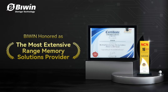
  June 28th had witnessed the successful hosting of the 16th NCN-ICT India Partner Summit 2024 at New Delhi, India. In the midst of the celebrations, BIWIN was honored with the esteemed “The Most Extensive Range Memory Solutions Provider of 2023 Award”, a reflection of its unwavering dedication to excellence and innovation.  BIWIN is the Winner of “The Most Extensive Range Memory Solutions Provider of 2023”  As an annual event that celebrates the achievements and contributions of key players in the ICT industry, the NCN-ICT Summit Awards brought together industry leaders, corporate executives, distributors, and resellers from India and abroad. It serves as a platform for industry professionals to gain insights into the latest innovations, share best practices, and explore new business opportunities.  Through a combination of online voting and evaluations conducted by a panel of experts and judges, this accolade is a testament to BIWIN’s commitment to delivering a comprehensive range of high-performance memory solutions and pushing forward with innovation and product expansion.  Recognized as a leader in the storage industry, BIWIN offers a comprehensive range of embedded flash-based storage solutions, including mobile phones, education devices, tablets, gaming machines, smart wearables, UAVs, action cameras, in-vehicle systems, DVR/NVRs, servers, OTT boxes, routers, and more. By providing tailored storage solutions, BIWIN supports innovation and advancement in these diverse technology areas.  Attending on behalf of BIWIN, Rajesh Khurana, Country Manager for Consumer Business, was honored to participate in the NCN-ICT Summit & Awards Night 2024 and accept the awards. He expressed heartfelt gratitude for the industry recognition and committed to integrating purpose-driven initiatives into BIWIN’s future work. Khurana emphasized that these efforts will not only honor the awards but also elevate BIWIN to new industry heights.  Rajesh Khurana was also privileged to be part of a renowned panel at the 16th Annual NCN-ICT Partners Summit, which was joined by top industry leaders from Geonix, Savex, Synersoft, Kaspersky and Micron. The discussion focused on the next big thing in ICT technology and examined the need for new business approaches, emerging ICT technologies, and changing business dynamics, as well as their impact on the vendor-partner ecosystem.  As noted by Rajesh Khurana, industry projections indicate that the memory market is expected to experience continued growth in the coming years, especially with the advancement of AI technologies, big data and Internet of Things which set to drive the demand to new levels. BIWIN will also endeavor to provide improved memory solutions for customers while contributing to the industry’s future development.
Key word:
Release time:2024-08-20 13:46 reading:889 Continue reading>>
GigaDevice GD32H7 Software Test Library (STL) Achieves TÜV Rheinland IEC 61508 Functional Safety Certification
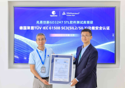
  GigaDevice (Stock Code: 603986), a leading semiconductor company announced today that its GD32H7 Software Test Library (STL) has received the IEC 61508 SC3 (SIL 2/SIL 3) functional safety certification from TÜV Rheinland, an international independent testing, inspection, and certification organization. This marks the first STL certification awarded by TÜV Rheinland to a Chinese semiconductor company. By adopting the GD32H7 Software Test Library (STL), users can efficiently develop industrial applications that comply with international functional safety standards. This certification attests to GigaDevice's strong capabilities in developing industrial products and supporting software, demonstrating that GigaDevice's functional safety management has reached international standards.  The certification ceremony was attended by Vincent Li, GigaDevice CTO and General Manager of MCU BU, and Bin Zhao, General Manager Cybersecurity & Functional Safety Greater China from TÜV Rheinland, along with other representatives from both companies.  IEC 61508 is a globally recognized foundational standard for industrial functional safety. It provides a fundamental evaluation method for the entire safety lifecycle of electrical, electronic, and programmable electronic (E/E/PE) systems and products used in safety applications. The standard comprehensively covers all aspects including functional safety management, system, hardware, software phases, support processes, safety analysis, product reliability, and product release. It aims to control the risks associated with systematic failures and random hardware failures to an acceptable level. To conclude, IEC 61508 has already become a crucial reference standard in key industries such as industrial, energy, water transport, and railways etc. Obtaining this certification is essential for entering industries that require advanced functional safety.  With the development of digitalization and intelligent technology, the importance of functional safety is increasing in industries such as industrial automation and digital energy. The GD32H7 Software Test Library (STL) with its exceptional detection capabilities, can accurately identify random hardware faults in safety-critical components like CPUs, SRAM, and Flash. This helps users flexibly utilize the GD32H7 series of ultra-high performance MCUs in developing complex computations, multimedia technologies, edge AI, and other advanced applications, significantly reducing safety risks. And the GD32H7 STL can be widely applicable to various end-user scenarios and can guarantee the reliability and safety of industrial applications. Besides, the Software Test Library will also be compatible with the GD32MCU that uses the same Arm® Cortex® M7 core. Furthermore, GigaDevice is actively advancing the certification of Software Test Library based on Arm® Cortex® M4 and Arm® Cortex® M33 cores, with plans to release soon. The significant initiatives will further strengthen GigaDevice's technological advantages in functional safety and meet the safety needs of various industry applications.  Vincent Li, GigaDevice CTO and General Manager of MCU BU, stated: "GigaDevice is unwavering in the commitment to excellence in quality, adopting a quality policy that involves full employee participation and entire product lifecycle coverage. The industrial sector is an important strategic focus for us, where we place significant emphasis on the functional safety of products and applications. We are deeply appreciative to the professional team at TÜV Rheinland for their assistance and recognition. Obtaining IEC 61508 SC3 (SIL 2/SIL 3) certification is a significant milestone for GigaDevice in functional safety management. It will greatly enhance the safety and ease of developing industrial applications for our users. In the future, we plan to progressively integrate this international standard to a broader product line, continuously reinforcing the reliability of our products and software, while driving the advancement of industry functional safety standards."  Bin Zhao, General Manager Cybersecurity & Functional Safety Greater China of TÜV Rheinland stated: "Congratulations to GigaDevice for becoming the first Chinese semiconductor company to receive the TÜV Rheinland STL certification! As an international third-party certification organization with a 150-year history, TÜV Rheinland is dedicated to providing technical support for the quality and safety of products and systems. During the project, our technical experts conducted a comprehensive safety verification of the GD32H7 STL throughout its lifecycle with a meticulous and responsible approach. We are very pleased to see that GigaDevice has met international standards in functional safety. In the future, we will continue to strengthen our collaboration to enhance the safety and reliability of GigaDevice's products, aiming to build outstanding market competitiveness."
Key word:
Release time:2024-08-19 15:48 reading:1341 Continue reading>>
Murata:Radisol Redefines Antenna Interference Countermeasures for Smartphones and Wearables
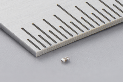
  Murata Manufacturing Co. Ltd announces the launch of Radisol – an innovative product designed to suppress interference between nearby antennas with low insertion loss, improving isolation and antenna radiation efficiency. This world-first solution is specifically engineered to meet the demands of compact modern devices like smartphones and wearables, offering benefits such as reduced power consumption, miniaturized construction, and enhanced communication quality. In addition, Radisol has been adopted by Motorola Mobility LLC (Headquarters: Libertyville, Illinois, USA, President: Sergio Buniac), in the new Edge series of smartphones scheduled to be released in August 2024. Motorola has realized a method of improving the characteristics of Wi-Fi® antennas by using Radisol.  As the demand for smaller smartphones and wearable devices grows, the number of antennas is also increasing to accommodate the expanding range of communication methods and bands. Additionally, MIMO technology to improve communication quality and speed is encouraging an increase in the number of antennas, while new designs such as foldable smartphones are encouraging antenna crowding. This has posed new difficulties, specifically the implications on antenna isolation and the decline in antenna effectiveness, as the interference of nearby antennas leads to a decrease in radiation efficiency.  Although discrete filters are a common solution for improving antenna isolation, they are not suitable when communication bands are closely situated, as insertion loss can impair antenna performance and occupy valuable board space. To address these challenges, Murata has created Radisol, a low-loss filter for antenna area that uses Murata’s unique ceramic multilayer technology and RF circuit design technology.  Antenna engineers usually construct a filter circuit using discrete L and C chip components to implement effective countermeasures. Instead, Radisol is just a single 0603-sized component that resolves the persisting challenges of antenna performance and packaging constraints. It effectively suppresses antenna interference, without significantly impacting the passband, and results in enhanced radiation efficiency and reduced power consumption.  Each Radisol component operates as a dedicated filter circuit designed specifically to mitigate the antenna interference associated with a specific communication band. The compact component integrates one capacitor and two inductors, providing band-stop filter characteristics within a single chip. Radisol features a unique design that utilizes the generation of lossless mutual inductance by two magnetically coupled coils. This setup forms a band-stop circuit with no notable insertion loss in the communication band. This specialized approach to antenna isolation enables Radisol to offer enhanced performance, with low insertion loss and high efficiency and system integration.  Included in the Radisol family are variants designed to effectively address the needs of common bands, including 2G & 5G Wi-Fi® as well as GPS signals. This eliminates the necessity of designing discrete filter circuits, simplifying the implementation of countermeasures. Murata will continue to expand upon the initial product lineup to further meet market demands and drive further innovation in antenna technology.  “By using Radisol engineers can address the challenges of modern communication devices without compromising signal integrity and radiation efficiency,” said Satoru Muto, General Manager of New Business Incubation Department at Murata. “By utilizing Murata's cutting-edge technology, this solution takes integration to a whole new level, eliminating the need for complex discrete filter circuits and saving valuable space.”  Radisol samples are available for evaluation and mass production has already begun in June 2024. To learn more about Radisol or to request samples, please contact your local Murata representative or visit here.
Key word:
Release time:2024-08-14 13:39 reading:831 Continue reading>>
Varistor and Thermistor: What Sets Them Apart
  Varistors and thermistors are two specialized resistors that break the mold of their traditional counterparts. While standard resistors offer constant opposition to current flow, varistors and thermistors are dynamic. Varistors act as voltage guardians, changing resistance to safeguard circuits from harmful surges. Thermistors, on the other hand, are temperature detectives, their resistance fluctuating with heat.  This blog explores the unique functionalities of varistors and thermistors, highlighting the key characteristics that differentiate them within the vast world of electronic components.  Varistor: The Voltage Dependent Resistor  A varistor, also known as a Voltage Dependent Resistor (VDR), is a special type of resistor whose resistance varies depending on the applied voltage. Under standard operating voltage, a varistor exhibits high resistance, acting like an open circuit. However, the varistor's resistance drops dramatically when a voltage surge exceeds a specific threshold. This sudden change allows excess current to flow through the varistor, diverting it away from sensitive circuit elements and protecting it from damage.  Varistors' common applications include protecting AC power lines and safeguarding electronic devices from transient voltage spikes caused by lightning strikes or power grid fluctuations.  Thermistor: The Temperature Sensitive Resistor  In contrast to varistors, thermistors are all about temperature. These components are essentially temperature-sensitive resistors (TSRs) whose resistance value changes significantly with fluctuations in temperature. There are two main types of thermistors:  PTC (Positive Temperature Coefficient): As the name suggests, the resistance of a PTC thermistor increases with rising temperature. These are often used in resettable fuses or self-regulating heating elements.  NTC (Negative Temperature Coefficient): Conversely, NTC thermistors exhibit a decrease in resistance as the temperature climbs. These are commonly employed in temperature sensors, fever thermometers, and temperature control systems.  Thermistors offer a wide range of applications in various industries. From monitoring engine coolant temperature in automobiles to regulating battery temperature in laptops, NTC thermistors play a vital role in ensuring optimal operation. On the other hand, PTC thermistors are used in circuit protection scenarios where a surge in temperature can trigger a safety response.  Differences Between Varistors and Thermistors  While both varistors and thermistors are crucial components, their functionalities and operating principles differ significantly:  Electrical Properties: Varistors exhibit non-linear resistance, dramatically changing based on voltage. Thermistors, on the other hand, display a more linear relationship between resistance and temperature.  Material Composition: Varistors are typically made of metal oxide ceramics, while thermistors can be constructed from various materials like ceramic semiconductors, polymers, or even thermistor beads.  Response to Environmental Factors: Varistors react to voltage spikes, while thermistors are sensitive to temperature variations.  Application Areas: Varistors excel in transient voltage protection, while thermistors shine in temperature sensing and control applications.  Varistor vs. Thermistor: When to Use Which?  Choosing between a varistor and a thermistor depends on the specific needs of your circuit:  Voltage Protection: A varistor is an ideal choice if your circuit requires protection from voltage spikes and transients.  Temperature Sensing: When accurate temperature measurement or control is crucial, NTC or PTC thermistors are the preferred components.  For example, a power supply circuit would likely utilize a varistor to safeguard against potential lightning strikes. At the same time, a battery pack might incorporate an NTC thermistor to monitor internal temperature for safety purposes.  Comparing Varistor and Thermistor Circuits  A simple circuit demonstrating a varistor application could involve connecting it in parallel with a sensitive electronic device across the power supply. In the event of a voltage surge, the varistor's resistance drops, diverting the excess current and protecting the device.  On the other hand, a thermistor circuit for temperature sensing might involve placing it in series with a current source. As the temperature rises, the thermistor's resistance decreases, causing a change in the current flow, which can be measured to determine the temperature.
Key word:
Release time:2024-07-25 11:04 reading:650 Continue reading>>
What are TVS diodes in safeguarding electronics
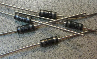
  In today’s interconnected world, electronic devices and systems are ubiquitous, powering our homes, workplaces, and communication networks. However, these devices are vulnerable to voltage transients—brief surges in voltage that can occur due to lightning strikes, electrostatic discharge (ESD), or switching transients in the electrical system.  To protect sensitive electronic components from such transients, Transient Voltage Suppressor TVS diodes play a crucial role. This article explores the functionality, applications, and importance of TVS diodes in safeguarding electronics.  What is a Transient Voltage Suppressor (TVS) Diode?A Transient Voltage Suppressor (TVS) diode is a semiconductor device used to protect sensitive electronic components from voltage spikes or transient voltages that could potentially damage them. These spikes can be caused by events such as lightning strikes, electrostatic discharge (ESD), or switching transients in the electrical system.  The TVS diode operates by providing a low-impedance path to divert excess voltage away from the protected components, thus limiting the voltage across them. When a transient voltage exceeds the breakdown voltage (also known as the clamping voltage or avalanche voltage) of the TVS diode, it starts to conduct, effectively shunting the excess current away from the protected circuit.  What are the features of TVS diodes?Fast Response Time: TVS diodes respond quickly to transient events, providing protection within nanoseconds to microseconds.  Low Clamping Voltage: The clamping voltage is the maximum voltage that the TVS diode allows to pass through to the protected circuit. It is typically lower than the voltage tolerance of the protected components, ensuring they remain safe.  High Surge Current Capability: TVS diodes are designed to handle high surge currents associated with transient events, protecting the circuit from damage.  Low Leakage Current: When not conducting, TVS diodes have low leakage current, minimizing power consumption and ensuring minimal impact on the protected circuit during normal operation.  Robustness: TVS diodes are robust devices, able to withstand multiple transient events without degradation in performance.  What are the applications of TVS diode?TVS diodes are commonly used in various applications, including:  Protection of integrated circuits (ICs), microcontrollers, and other semiconductor devices from ESD and voltage transients.  Protection of communication ports (such as USB, Ethernet, HDMI) and data lines in electronic equipment.  Surge protection for power supply lines, signal lines, and sensor inputs in industrial and automotive electronics.  Protection of sensitive electronic equipment against lightning-induced surges in telecommunications, power distribution, and other infrastructure.  What’s the difference between TVS Diodes and Zener Diodes?TVS (Transient Voltage Suppressor) diodes and Zener diodes are both semiconductor devices used for voltage regulation, but they serve different purposes and operate in different ways. Here are the key differences between TVS diodes and Zener diodes:  Purpose:  • TVS Diodes: TVS diodes are primarily used for transient voltage suppression, meaning they protect electronic circuits from voltage spikes or transients caused by events like lightning strikes, electrostatic discharge (ESD), or inductive switching. Their main function is to provide surge protection and prevent damage to sensitive components.  • Zener Diodes: Zener diodes are used for voltage regulation and voltage reference. They operate in the breakdown region and maintain a constant voltage across their terminals when reverse biased. Zener diodes are commonly used in voltage regulation circuits, voltage clamping circuits, and voltage reference circuits.  Operating Principle:  • TVS Diodes: TVS diodes operate by avalanche breakdown or Zener breakdown. When the voltage across a TVS diode exceeds its breakdown voltage, it starts to conduct heavily, providing a low-impedance path for excess current and diverting it away from the protected circuit.  • Zener Diodes: Zener diodes operate in the reverse-biased breakdown region, where they maintain a constant voltage (known as the Zener voltage) across their terminals. They regulate voltage by allowing current to flow in the reverse direction when the applied voltage exceeds the Zener voltage.  Voltage Characteristics:  • TVS Diodes: TVS diodes typically have a very low clamping voltage (Vc) and are designed to handle high surge currents associated with transient events. They are optimized for fast response times and high-energy absorption capabilities.  • Zener Diodes: Zener diodes have a well-defined breakdown voltage (Vz) at which they operate. The voltage across a Zener diode remains relatively constant over a wide range of currents when reverse biased, making them suitable for voltage regulation applications.  Applications:  • TVS Diodes: TVS diodes are used in applications requiring protection against voltage transients, such as in power supplies, communication ports (USB, Ethernet), data lines, and electronic equipment exposed to harsh environments or prone to ESD.  • Zener Diodes: Zener diodes find applications in voltage regulation circuits, voltage references, voltage clamping circuits, reverse voltage protection, and precision voltage measurement circuits.  How do TVS diodes work?  TVS diodes work by providing a low-impedance path for excess voltage, diverting it away from sensitive electronic components and limiting the voltage across them to safe levels. They operate based on two main mechanisms: avalanche breakdown and Zener breakdown. Here’s how TVS diodes work:  Avalanche BreakdownTVS diodes are typically fabricated with a highly doped semiconductor material that has a narrow depletion region. When the diode is reverse-biased (i.e., the voltage applied across it is in the opposite direction of its normal operation), the electric field across the depletion region increases.  If the applied reverse voltage exceeds a certain threshold known as the breakdown voltage (also called clamping voltage or avalanche voltage), the strong electric field can accelerate charge carriers (electrons and holes) to high energies.  These high-energy charge carriers collide with other atoms in the semiconductor lattice, generating additional charge carriers through impact ionization. This process cascades, resulting in a sudden increase in current flow through the diode.  As a result, the TVS diode effectively clamps the voltage across its terminals at the breakdown voltage, providing a low-impedance path for excess current and limiting the voltage seen by the protected circuit.  Zener BreakdownIn addition to avalanche breakdown, some TVS diodes may also utilize Zener breakdown to provide transient voltage suppression. Zener breakdown occurs when the reverse-biased diode operates in its Zener breakdown region.  In this region, the diode behaves as a voltage regulator, maintaining a relatively constant voltage (known as the Zener voltage) across its terminals. When the applied reverse voltage exceeds the Zener voltage, the diode starts conducting heavily, effectively clamping the voltage across it.  What causes a TVS diode to fail?TVS diodes are designed to withstand high levels of transient voltage and provide protection to sensitive electronic components. However, like any electronic component, TVS diodes can fail under certain conditions. Here are some common causes of TVS diode failure:  Overvoltage Conditions: If the transient voltage exceeds the maximum rated clamping voltage (avalanche or Zener breakdown voltage) of the TVS diode, it may fail to suppress the transient effectively. This can happen if the transient event is exceptionally severe or if the TVS diode is underspecified for the application.  Overcurrent Conditions: Excessive current flowing through the TVS diode, either due to a high-energy transient event or a sustained fault condition, can cause the diode to fail. Overcurrent can lead to thermal overstress, causing the diode to overheat and potentially short or open circuit.  Reverse Polarity: Applying a reverse voltage beyond the maximum reverse voltage rating of the TVS diode can cause it to fail. This can occur due to improper installation or incorrect wiring in the circuit.  End-of-Life Wear-Out: Like all semiconductor devices, TVS diodes have a limited lifespan, and their performance may degrade over time due to factors such as aging, temperature cycling, and electrical stress. As the diode approaches the end of its life, its ability to suppress transients effectively may diminish, leading to failure.  Excessive Power Dissipation: TVS diodes are specified with maximum power dissipation ratings. Exceeding these ratings, either due to sustained overvoltage conditions or prolonged exposure to transient events, can cause the diode to overheat and fail.  Manufacturing Defects: Rarely, TVS diodes may fail due to manufacturing defects such as material impurities, processing errors, or incomplete encapsulation. These defects can compromise the electrical and thermal performance of the diode, leading to premature failure.  Improper Handling or Installation: Mishandling or improper installation of TVS diodes, such as mechanical stress during assembly, soldering defects, or exposure to corrosive environments, can lead to physical damage or degradation of the diode, resulting in failure.  ConclusionTVS diodes are essential components in protecting electronic devices and systems from voltage transients. Their ability to clamp voltages and divert excess current away from sensitive components plays a vital role in ensuring the reliability and durability of modern electronics. As the demand for high-performance and reliable electronic products continues to grow, the importance of TVS diodes in safeguarding electronics will only increase, making them indispensable in today’s interconnected world.
Key word:
Release time:2024-07-16 13:08 reading:627 Continue reading>>
Why use tantalum capacitors in circuit board assembly
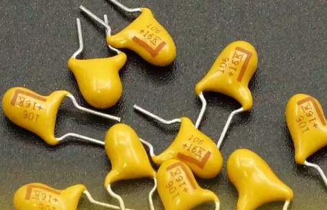
  A capacitor is a component made up of two metal films placed close together and separated by an insulating material. The two pieces of metal are called pole plates, and the material in between is called the dielectric. The key reason why capacitors can be divided into different types is that there are certain differences. There are many differences not only in materials, but even in design principles, working principles and structures.  Tantalum is the second most precious metal after precious metals, and is one of the most expensive of the rare metals. Tantalum capacitors are electronic components with tantalum as the main component, small in size and high in capacity, installed on printed circuit boards of many small electrical/electronic devices such as personal computers, cell phones and digital.  What is tantalum capacitor  Electrolytic capacitors with tantalum as a component are called tantalum capacitors. They are polarized capacitors with good frequency and stability. It has a tantalum anode and electrolytic capacitor.  Tantalum capacitors have been used in electronic circuits since the 1950’s. Today they still play an important role in many different types of electronics.  Tantalum capacitors are a kind of electronic components which is widely used in the industries. They can be found in every electronic product such as speakers and cell phones, TV and microwave oven, computer and headphone.  What is a tantalum capacitor used for  Tantalum capacitors are small, high-capacity capacitors. Tantalum capacitors come in various shapes and are made into small and chip components suitable for surface mounting. Tantalum capacitors are used not only in military communications, but also in aviation, aerospace and other fields, and are widely used in industrial control and vision, in frequency equipment, communication instruments and other products.  Due to the thin oxide film, the distance between the two pole plates of tantalum capacitors is very close, and there is almost no inductive reactance, which is very sensitive, so the charging and discharging speed is very fast. In addition, because there is no electrolyte inside the tantalum capacitor, it is very suitable for working under high temperature.  Tantalum capacitors are used in many different applications, including:  ●Power supplies and inverters  ●Radio frequency systems  ●Telecommunications equipment  ●Scientific instrumentation equipment (e.g., oscilloscopes)  What are the pros and cons of tantalum capacitors  Tantalum capacitors are a good choice for electronic applications. They are used in power supplies and other low-power devices, as they provide high capacitance while maintaining low leakage currents. They also have excellent ESR (equivalent series resistance), which means that they can withstand high voltages without affecting their performance.  Pros  Tantalum capacitors have several advantages over traditional aluminum electrolytic capacitors:  ●Tantalum has better conductivity than aluminum, making it ideal for applications where heat dissipation is important (such as switching power supplies).  ●It has lower drift rate than aluminum due to its higher dielectric constants (dielectric constant is the property of an insulating material that determines how easily electricity flows through it).  ●You can use tantalum capacitors with no risk of arcing or explosions because there’s no need for venting holes on them—and if you do want one then you’ll be able to find one at any electronics store!  Cons  There are some disadvantages of tantalum capacitors:  ●Tantalum capacitors are more expensive than ceramic capacitors, and they can be up to twice as expensive as aluminum electrolytic capacitors.  ●It takes time for the capacitor to break in and get its full potential.  What are the features of tantalum capacitor  The Reliability:  Tantalum capacitors are reliable, and they have a longer service life than other types of capacitors. They have high current handling capability with low losses in comparison to other ceramic types such as alumina/silicon carbide (ACSR).  The low power consumption  The low power consumption is another advantage of tantalum capacitors. Since they have a low voltage drop, they require less energy to run at full capacity. This means that you will use less electricity per day than you would with other types of capacitors. Another benefit is that your system will generate less heat during operation so there’s no need for fans or cooling systems.  The high energy density  The high energy density of tantalum capacitors is a great substitute for the traditional ceramic capacitors. This is because it has a high electrical conductivity, which makes it an excellent choice for use in applications that require high power densities or large currents.  In addition to its excellent electrical properties, tantalum capacitors also have the ability to be stacked together to form larger assemblies for even greater power handling capacity. These stacking designs can be used as independent units or as building blocks toward larger projects.  Resistance to high temperatures and voltages  Tantalum capacitors have low temperature coefficients and can withstand high voltage applications without any problems, unlike the aluminum electrolytic type which has a low coefficient of thermal expansion at elevated temperatures.What is polarity on tantalum capacitor  Tantalum capacitor has one-way conductivity, which is called “polarity”, when using, the current should be accessed according to the positive and negative direction of the power supply, the anode (positive) of the capacitor is connected to the “+” pole of the power supply, and the cathode (negative) is connected to the “-” pole of the power supply, if the capacitor is connected wrongly, not only the capacitor can not play a role, but also the leakage current is very large, and the core will be hot in a short time, and the oxide film will be destroyed and then fail.  In general, positive polarity means positive terminal of the battery is connected to positive terminal of the capacitor while negative polarity means that it is connected to negative terminal of the capacitor.
Release time:2024-07-05 14:09 reading:585 Continue reading>>
ROHM Develops a Novel VCSELED™ Infrared Light Source that Combines Features of VCSELs and LEDs
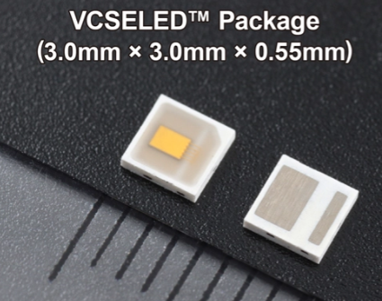
  ROHM has established VCSELED™, a new infrared light source technology that encapsulates a VCSEL (Vertical Cavity Surface Emitting Laser) element in a resin optical diffusion material for laser light. ROHM is currently developing this technology for commercialization as a light source for improving vehicle Driver Monitoring Systems (DMS) and In-Cabin Monitoring Systems (IMS).  To further enhance automotive safety, driver monitoring systems are increasingly being installed in vehicles equipped with Advanced Driver Assistance Systems (ADAS) to detect drowsiness, sleepiness, and distracted driving. In Japan, the Ministry of Land, Infrastructure, Transport, and Tourism (MLIT) has created guidelines that define the design and functions of the system, and in the EU, there are plans to make installation mandatory in all new vehicles sold in Europe from July 2024 onwards. Automakers and suppliers are also developing in-vehicle monitoring systems to detect occupants other than the driver, and there is a growing awareness of the need for high-performance light sources that enable detection systems to function with greater precision.  In response, ROHM has developed VCSELED™ that achieves high-accuracy sensing. Minimal wavelength temperature variation combined with a wide emission beam angle make it ideal not only for in-vehicle monitoring systems, but also contribute to improving the accuracy and performance of inspection systems for robots and industrial equipment as well as spatial recognition and ranging systems.  VCSELED™ extends the beam (irradiation) angle similar to LEDs by combining a high-performance VCSEL element and light diffusion material to enable sensing over a wider area with higher accuracy than VCSELs. What’s more, the light emitting element and light diffuser are integrated into a compact package, contributing to smaller, thinner applications.  The VCSEL element used in VCSELED™ features a narrow emission wavelength bandwidth of 4nm, approximately one-seventh that of LEDs. This characteristic improves resolution performance on the receiving side while eliminating the red glow often associated with LEDs. At the same time, a wavelength temperature variation of 0.072nm/°C - less than one-fourth that of LEDs (0.3nm/°C) - allows for high-accuracy sensing unaffected by temperature changes. Furthermore, the response time when emitting light is 2ns, approx. 7.5 times faster than LEDs, contributing to higher performance in ToF (Time of Flight) applications that use infrared light to measure distance.  ROHM is working on commercializing VCSELED™ as a new technology brand for infrared light source components. Prototype samples is available for purchase now, with mass production samples for consumer scheduled for release in October 2024 and automotive use in 2025, respectively. To obtain samples, please contact a sales representative or visit the contact page on ROHM’s website. Going forward, we will continue to develop laser light source technology for in-vehicle monitoring and other systems.  TerminologyVCSEL  Short for Vertical Cavity Surface Emitting Laser. Although conventionally used for communication, it is increasingly being adopted in recent years as a light source for the optical block in sensing systems.  DMS  Stands for Driver Monitoring System. A safe driving assistance function that detects whether the driver can continue safe driving based on facial and eye movements and provides alerts via sounds and/or text to prevent accidents before they occur.  IMS(ICMS)  Abbreviation for In-Cabin Monitoring System. This system expands the detection range to include front and rear passenger seats, occupant recognition, and biometric sensing to improve safety and comfort.  Red Glow  When high power infrared LEDs are used in sensors and other devices, there is a possibility that wavelengths close to those of visible light will be emitted that can be detected by the human eye. In this case, the sensor appears slightly red, hence the term “red glow”.
Key word:
Release time:2024-06-27 13:42 reading:591 Continue reading>>
novosns:Technical Sharing | The Introduction of Gate Drivers and the Applications
  1) Introduction of the Gate Drivers  Gate driver is a buffer circuit between the low-voltage controller and the high-power circuit, which is used to amplify the control signals of the controller for more effective turn-on and turn-off of power devices.  1. The functions of gate driver are as follows  - Gate driver can convert the low-voltage signal from the controller to higher-voltage drive signal, so as to achieve stable turn-on and turn-off of power devices.  - Gate driver can provide transient source and sink peak currents, which can improve the switching speed of power devices and reduce the switching loss.  - Gate driver can effectively isolate the noise of high-power circuits and protect sensitive circuits against interference.  - Gate driver typically integrates protection functions to effectively prevent damages to power devices.  It can be seen that gate driver is used to ensure better performance of power devices in the system.  2. There are four types of common power devices  - Si-MOSFET devices, which withstand voltage of 20V-650V and are suitable for low-power systems.  - Si-IGBT devices, which withstand voltage of greater than 650V and provide a strong current endurance capability. This type is suitable for high-voltage and high-power systems.  --- Both Si-MOSFET and Si-IGBT are Si-based power devices that have been widely used, and their manufacturing technologies are mature and stable.  - SiC-MOSFET devices, which provide withstand voltage range comparable to IGBT, but feature fast switching speed and low switching loss. They are more suitable for high-voltage and high-power systems.  - GaN devices, currently constrained by the manufacturing technology, typically have a withstand voltage of less than 650V, but provide obviously advantageous switching performance. This power device type is suitable for high-frequency and high-power systems.  --- SiC-MOSFET and GaN devices are wide bandgap semiconductors that boast significant performance advantages over Si-based ones, and will have a broad range of applications in the future.  3. NOVOSENSE gate drivers  Different power devices have varied requirements for gate drivers. Currently, NOVOSENSE has developed driver products suitable for these four types of power devices.  4. Switching process of power devices  How does a gate driver control the turn-on and turn-off of power devices? Below is a detailed explanation of the switching process of power devices. In power devices, there are equivalent parasitic capacitances, such as CGS, CGD and CDS. The switching process of a power device can be equivalent to the charging and discharging process of its parasitic capacitances.  4.1 Turn-on process  In the turn-on process, the driver IC connects the output signal to the driver power supply through an internal source current MOS, and charges CGS and discharges CGD through a gate resistor.  - (t0-t1) stage: The gate current charges CGS, and VGS gradually increases. At this point, the power device is still turned off.  - (t1-t2) stage: When VGS increases to a value greater than the gate threshold voltage Vth, the power device begins to turn on, and IDS increases with VGS until it reaches the maximum value.  - (t2-t3) stage: This is the Miller Plateau period, where the gate current mainly discharges CGD, and VDS begins to decrease. The device is fully turned on.  - (t3-t4) stage: The gate current continues to charge CGS, and VGS gradually increases to the power supply voltage. When the gate current reduces to zero, the turn-on process ends. The turn-on loss of the power device mainly occurs at the t1-t3 stage.  4.2 Turn-off process  In the turn-off process, the driver IC connects the output signal to the GND through an internal sink current MOS, and discharges CGS and charges CGD through a gate resistor.  - (t0-t1) stage: The gate current mainly discharges CGS, and VGS gradually decreases.  - (t1-t2) stage: This is the Miller Plateau period, where the gate current mainly charges CGD, and VDS begins to increase. When the voltage reaches VDC, the Miller Plateau ends.  - (t2-t3) stage: IDS begins to decrease. When VGS decreases to Vth, IDS drops to zero, and the power device is completely turned off.  - (t3-t4) stage: The gate current continues to discharge CGS, and VGS eventually drops to zero. The turn-off process ends. The turn-off loss of the power device mainly occurs at the t1-t3 stage.  It can be seen from the analysis above that shortening the t1-t3 stage can effectively reduce the switching loss of power devices.  4.3 Three types of common driver IC  At present, there are three types of commonly used driver ICs, namely non-isolated low-side drivers, non-isolated half-bridge drivers, and isolated drivers.  - Non-isolated low-side drivers are only suitable for power devices with a reference to GND, and provide dual-channel or single-channel driving capability. Non-isolated drivers are relatively simple to implement, requiring only single power supply. They are mainly used in low-voltage systems, such as AC/DC converters, electric tools, and low-voltage DC/DC converters. Currently, NOVOSENSE offers non-isolated low-side driver ICs including NSD1026V and NSD1015.  - Non-isolated half-bridge drivers are used in power systems with a half-bridge configuration. The withstand voltage of the high and low sides is usually achieved through level shifting or isolation, ranging from 200V to 600V. To prevent shoot-through, half-bridge drivers provide an interlock function. When a non-isolated half-bridge driver is used in a system, single power supply plus bootstrap power is typically adopted. This driver IC type is mainly used in low-voltage or high-voltage systems, such as AC/DC converters, motor drives, and on-board DC/DC converters. Currently, the half-bridge driver ICs from NOVOSENSE include NSD1624 and NSD1224.  - Isolated drivers use an internal isolation barrier to physically isolate high and low voltages. Isolated drivers provide flexibility in application. Single-channel and dual-channel isolated drivers are available for low-side, high-side, or half-bridge applications. To achieve primary and secondary isolation in the system, the high-voltage side requires an isolated power supply, making the power supply system relatively complex. Isolated drivers are mainly used in high-voltage systems, such as electric drives, photovoltaic inverters, and OBCs. Currently, NOVOSENSE offers NSI6602 dual-channel isolated driver IC, NSI6601/NSI6601M single-channel isolated driver IC, NSI6801 opto-compatible isolated single-channel driver IC, and NSI6611/NSI68515 smart isolated driver IC.  2) Introduction to Isolation Solutions  In a high-voltage power system, there is usually isolation between high voltage and high voltage, as well as between high voltage and low voltage. Why is isolation driver needed? First, an isolated driver can avoid harm to human body caused by high-voltage electricity, and meet safety standards through isolation. Second, it can protect the control system from damages that can be caused by lightning strikes and high voltage transients. Third, an isolated driver can eliminate ground loops and reduce interference from the high voltage side to the low voltage side. Fourth, it can realize voltage or current change and energy transfer.  There are three commonly used isolation schemes. The first is optocoupler isolation, which achieves signal transmission through light-emitting diodes and phototransistors. This isolation scheme is low-cost, but provides weak CMTI (Common Mode Transient Immunity), limited temperature range, and short service life. The second isolation scheme is magnetic isolation, where the chip integrates micro-transformer and electronic circuit to achieve signal transmission. The magnetic isolation chips deliver benefits such as long lifetime, wide temperature range, and strong CMTI, but involve complex technology, high cost, and prominent EMI issue. The third isolation scheme is capacitive isolation, which achieves signal transmission through isolation capacitors and electronic circuits. It usually uses silicon dioxide (SiO2) as the insulating material. The capacitive isolation scheme features low cost, long isolation life, wide temperature range, and strong CMTI. NOVOSENSE adopts the capacitive isolation scheme.  NOVOSENSE isolation solution  Isolated driver ICs from NOVOSENSE usually have two dies – the primary die on the input side and the secondary die on the output side. There is a physical isolation between the dies. Two isolation capacitors are connected in series on the die to achieve double insulation capability. If one of the dies experiences an EOS failure, the driver IC can still maintain basic insulation capability. The top and bottom substrates of the two isolation capacitors are insulated using SiO2, which can ensure stable material properties, good chip consistency, and long isolation life. The top substrates of the two isolation capacitors are connected by metal wires for signal transmission. NOVOSENSE’s isolated driver ICs can withstand surge voltage up to 12kV and 8kV transient insulation voltage test, far exceeding the insulation requirements of high-voltage systems.  The communication between the dies adopts the differential OOK modulation scheme, which ensures stable and reliable communication. The input signal is modulated at a high frequency and then transmitted from the primary die to the high-voltage die through the isolation capacitor, with the modulation frequency at a level of over 100 MHz. A proprietary CMTI modular circuit is added at the input side of the differential signal, allowing the IC to achieve a stronger CMTI capability up to 150V/ns. For power systems with a high dv/dt, the IC can still work stably without abnormal wave emission.
Key word:
Release time:2024-06-21 11:23 reading:743 Continue reading>>
Renesas’ R-Car Open Access Platform Accelerates Software-Defined Vehicle Development With Market-Ready Software
  Renesas Electronics Corporation (TSE:6723), a premier supplier of advanced semiconductor solutions, today launched R-Car Open Access (RoX), a development platform for software-defined vehicles (SDVs) that integrates all essential hardware, operating systems (OS), software and tools needed for automotive developers to rapidly develop next-generation vehicles with secure and continuous software updates. Designed for the Renesas R-Car family of system on chips (SoCs) and microcontrollers (MCUs), the SDV platform includes comprehensive tools for the seamless deployment of AI applications. By pre-integrating all fundamental layers required to develop SDVs, RoX drastically reduces the complexities for car OEMs and Tier 1 suppliers, saving time and money.  The advent of SDVs represents a major step forward in automotive technology – accelerating toward more driving autonomy, electrification and connected experiences. Cars have to be aware of the 360-degree surrounding space with ASIL D levels of sensing, processing and control to deliver safety and autonomy applications. The in-cabin experiences for drivers and passengers are being revolutionized. As a result, modern electrical/electronics (E/E) architecture depends on software to control vehicle functions, manage real-time data networks across different ECU zones, and provide customer differentiation. It has become more difficult to maintain and upgrade these complex software stacks while ensuring the highest levels of safety. Renesas’ customizable solution solves these challenges by offering a cloud-native development environment and a simulation platform, supporting the software-first approach and parallel hardware and software development.  Out-of-box Platform with Market-Ready Software Stacks  The flexible RoX SDV platform is available in two versions. “RoX Whitebox” is an open, easily accessible software package that includes royalty-free OS and hypervisor software such as Android Automotive OS, FreeRTOS, Linux, Xen and Zephyr RTOS, as well as reference applications designed for specific domain systems. “RoX Licensed” is based on industry-proven commercial software solutions, such as QNX and Red Hat In-Vehicle Operating System, as well as AUTOSAR-compliant software and SAFERTOS®. It is pre-integrated and tested to run on Renesas’ R-Car SoCs and MCUs and includes pre-validated software stacks from STRADVISION for Advanced Driver Assistance Systems (ADAS) and Candera CGI Studio for in-vehicle infotainment (IVI), to name a few. These software solutions can be easily productized and customized or expanded depending on OEMs’ needs.  With the RoX SDV platform, automotive system engineers can start building their software immediately using a highly integrated toolchain even before the hardware is available. This is made possible through the cloud environment and the virtual development platform, which let developers design, debug in simulation, and verify their software before deploying on live SoCs and MCUs. The virtual development platform includes the Renesas Fast Simulator (RFS) as well as partner solutions such as ASTC VLAB VDM and Synopsys Virtualizer Development Kit (VDK) to provide broad coverage of simulation speed, features and use cases.  For seamless end-to-end AI development, RoX offers the AI Workbench to enable developers to validate and optimize their models and test their AI applications all in the cloud, either on the virtual development platform or on Renesas board farms. A wide range of AI models, automated pipelines, as well as a specific hybrid compiler toolchain (HyCo) are available to support the rapid AI deployment on the R-Car heterogeneous compute platform across generations of SoCs.  AWS Cloud Services Now Available  The RoX SDV platform now supports Amazon Web Services (AWS) cloud computing services as part of the AI Workbench development environment. With the Renesas R-Car SDK (Software Development Kit) containerized in the AWS cloud environment, developers can innovate and optimize their designs more efficiently. This tight integration allows them to simulate and test hardware and software combinations instantly and deploy AI applications that seamlessly run on R-Car devices.  Scalable R-Car Gen 5 Family  The RoX SDV platform is designed for current generation R-Car SoCs, the upcoming R-Car Gen 5 MCU/SoC Family, and future devices. The SDV platform provides car OEMs and Tier1 suppliers the flexibility to design a broad range of scalable compute solutions for ADAS, IVI, gateway and cross-domain fusion systems as well as body control, domain and zone control systems.  Renesas’ R-Car Gen 5 is currently the only hardware architecture in the industry that can accommodate the full range of processing requirements – from zonal ECUs to high-end central compute, serving from entry-level vehicles to luxury-class models. Thanks to a new unified hardware architecture based on Arm® CPU cores, customers developing with the R-Car Gen 5 devices will be able to reuse the same software and tools across diverse E/E applications that span car models and generations, preserving their engineering investments. Renesas’ high-performance SoC products will offer both domain-specific and cross-domain solutions using application processing, large display capabilities, sensor connectivity, GPU and AI processing.  “RoX is a significant advancement that will speed up the shift-left approach for software-defined vehicles,” said Vivek Bhan, Senior Vice President and General Manager of High Performance Computing at Renesas. “Today, car OEMs and Tier1 suppliers are heavily investing in software development and maintenance. Renesas understands this challenge and is closely working with them to deliver a flexible, ready-to-deploy development solution that can be maintained throughout the vehicle’s lifespan. The RoX platform empowers our customers to design vehicles that deliver new value and bring improved safety and delightful comfort experiences to drivers and passengers.”  “At AWS, we’re committed to helping our customers and partners accelerate development and bring innovation to drivers faster than ever before,” said Andrea Ketzer, Director of Technology Strategy, Automotive & Manufacturing at AWS. “With Renesas’ R-Car Gen 5 devices supported by the AI Workbench on AWS, customers will achieve faster and more validated simulations and the ability to develop independently of hardware. This step change in development will drive the industry forward and place software innovation at the forefront of mobility.”  According to TechInsights, the market shift to domain, zonal and centralized architectures will translate to a growing processor market, incorporating SoCs and MCUs, worth $25.9 billion by 2031. “Being able to maintain and upgrade complex software stacks that incorporate operating systems, hypervisors and other functional software stacks will thus become an increasingly critical element of the supply chain,” said Asif Anwar, Executive Director of Automotive End Market Research at TechInsights. “By also being able to offer cloud-native environments to support a software-first approach to development and testing of the hardware, the Renesas RoX SDV platform offers a ready-built ecosystem that encompasses these elements in support of a scalable portfolio of next generation R-Car Gen 5 processors to address this sizable market.”  Renesas’ R-Car Open Access Platform is being demonstrated at the AWS Summit Japan in Tokyo from June 20-21.  RoX SDV Platform Partners:  Operating System/Hypervisor Partners  QNX  Red Hat  Vector AUTOSAR  WITTENSTEIN SAFERTOS®  Software Stack Partners  Candera CGI Studio  EPAM AosEdge  Excelfore eSync  MM Solutions  STRADVISION SVNet  Nullmax  Development Tools Partners  ASTC VLAB Works  Synopsys Virtualizer Development Kit (VDK)  Cloud Partners  AWS  Microsoft Azure  Availability  The R-Car Open Access Platform is available today with the option to license. Open-source OS, commercial OS, full application software stacks, virtual development, cloud infrastructure and debugging and emulation tools are available by Renesas or through partners. Additional information about the development platform is available here and information about the R-Car Gen 5 Family can be found here. Please contact your local sales teams for more details.
Key word:
Release time:2024-06-20 10:53 reading:1306 Continue reading>>
EMC Components : Guardians of Electronic Devices
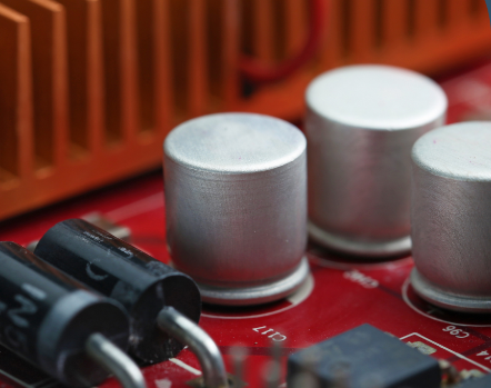
  Electromagnetic interference (EMI) is a pervasive force in our modern world. It emanates from various sources such as radio waves, power lines, and even the devices we use daily. EMI can disrupt the operation of electronic devices, causing malfunctions, data corruption, or complete failure. This interference not only affects the device itself but can also radiate outward, potentially interfering with other nearby electronic systems.  Electromagnetic compatibility EMC components are crucial for addressing electromagnetic interference emissions and susceptibility issues. The correct selection and use of these components are prerequisites for electromagnetic compatibility design.  Therefore, we must have a deep understanding of these components in order to design electronic and electrical products that meet standard requirements and offer the best cost-effectiveness. Each electronic component has its own characteristics, so this article will discuss some common electronic components and circuit design techniques to reduce or suppress electromagnetic compatibility issues.  There are two basic groups of electronic components: leaded and lead-free components. Leaded components have parasitic effects, especially at high frequencies. The leads form a small inductance, approximately 1nH/mm/lead. The ends of the leads also produce a small capacitance effect, around 4pF. Therefore, the length of the leads should be kept as short as possible. Compared to leaded components, lead-free surface-mount components have smaller parasitic effects. Typical values are: 0.5nH parasitic inductance and around 0.3pF terminal capacitance.  EMC components are specialized electronic parts designed to mitigate the effects of electromagnetic interference. They act as shields, filters, and absorbers, safeguarding sensitive electronic circuits from unwanted electromagnetic disturbances. These components come in various forms, each serving a unique purpose in the quest for electromagnetic compatibility.  CapacitorsCapacitors are indispensable elements in EMC design, serving as robust tools for both filtering and bypassing unwanted noise and signals.  At their core, capacitors store and release electrical energy, but in the realm of EMC, they serve a dual purpose. Firstly, capacitors act as filters, blocking high-frequency noise and interference from entering sensitive circuits. By strategically placing capacitors in signal paths or power lines, designers can effectively attenuate EMI, preserving signal integrity and device performance.  Secondly, capacitors act as bypass components, providing a low-impedance path for high-frequency noise to dissipate harmlessly to ground. This prevents noise from propagating through the circuit and interfering with critical operations.  Ferrite Beads and ChokesFerrite beads and chokes are passive components commonly used to suppress high-frequency noise in electronic circuits. By introducing impedance to the flow of high-frequency signals, these components effectively filter out electromagnetic interference. They are often found in power lines, signal cables, and printed circuit boards, where they help maintain signal integrity and prevent interference from disrupting sensitive electronic components.  EMI FiltersEMI filters are active or passive devices that suppress conducted electromagnetic interference by attenuating noise on power lines and signal cables. These filters typically employ a combination of capacitors, inductors, and resistors to shunt high-frequency noise to ground, ensuring that only clean power reaches the electronic device. EMI filters are crucial in applications where strict electromagnetic compatibility standards must be met, such as medical devices, automotive electronics, and telecommunications equipment.  InductorsInductors, vital EMC components, establish a connection between magnetic and electric fields, offering sensitivity crucial for addressing electromagnetic interference (EMI). These components, akin to capacitors, tackle various EMC challenges effectively. There are two fundamental types: open-loop and closed-loop, distinguished by their magnetic field paths. Open-loop inductors, with magnetic fields traversing air, can induce radiation and EMI concerns. Axial winding is preferable over rod or coil designs to confine the magnetic field within the core.  Conversely, closed-loop inductors enclose the magnetic field entirely within a magnetic core, rendering them ideal for circuit design albeit pricier. Ferrite-core inductors are particularly suited for EMC applications due to their capacity to operate at high frequencies, ensuring efficient EMI suppression. In EMC endeavors, ferrite beads and clips emerge as specialized inductor types, catering to unique interference challenges.  Shielding MaterialsShielding materials, such as conductive foils, tapes, and coatings, create a barrier between sensitive electronic components and external electromagnetic fields. They prevent electromagnetic interference from penetrating or escaping from electronic enclosures, thereby minimizing the risk of interference-induced malfunctions. Shielding materials are widely used in consumer electronics, industrial machinery, and aerospace systems to ensure reliable operation in electromagnetic environments.  Surge SuppressorsSurge suppressors, also known as transient voltage suppressors (TVS), protect electronic circuits from voltage spikes and transient surges caused by lightning strikes, electrostatic discharge (ESD), or switching events. These components rapidly divert excess energy away from sensitive electronic components, preventing damage and ensuring the longevity of electronic devices. Surge suppressors find applications in power supplies, data communication systems, and automotive electronics, where robust protection against transient events is essential.  ConclusionThe role of EMC components in ensuring the reliability and performance of electronic devices cannot be understated. From ferrite beads and EMI filters to shielding materials and surge suppressors, these unsung heroes silently guard our electronic world against the invisible forces of electromagnetic interference. As technology marches forward, the importance of EMC components will only continue to grow, shaping the future of electronics in an interconnected world.
Key word:
Release time:2024-06-03 15:43 reading:846 Continue reading>>

Turn to

/ 82

  • Week of hot material
  • Material in short supply seckilling
model brand Quote
TL431ACLPR Texas Instruments
CDZVT2R20B ROHM Semiconductor
RB751G-40T2R ROHM Semiconductor
BD71847AMWV-E2 ROHM Semiconductor
MC33074DR2G onsemi
model brand To snap up
ESR03EZPJ151 ROHM Semiconductor
TPS63050YFFR Texas Instruments
IPZ40N04S5L4R8ATMA1 Infineon Technologies
BP3621 ROHM Semiconductor
BU33JA2MNVX-CTL ROHM Semiconductor
STM32F429IGT6 STMicroelectronics
Hot labels
ROHM
IC
Averlogic
Intel
Samsung
IoT
AI
Sensor
Chip
About us

Qr code of ameya360 official account

Identify TWO-DIMENSIONAL code, you can pay attention to

AMEYA360 mall (www.ameya360.com) was launched in 2011. Now there are more than 3,500 high-quality suppliers, including 6 million product model data, and more than 1 million component stocks for purchase. Products cover MCU+ memory + power chip +IGBT+MOS tube + op amp + RF Bluetooth + sensor + resistor capacitance inductor + connector and other fields. main business of platform covers spot sales of electronic components, BOM distribution and product supporting materials, providing one-stop purchasing and sales services for our customers.
Please enter the verification code in the image below:

verification code