Nidec Precision Develops TapSense, the World’s Thinnest Linear Resonant Actuator
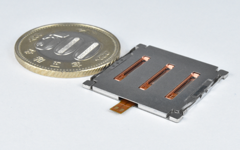
  Nidec Precision Corporation (“Nidec Precision” or the “Company”), a member of Nidec Corporation’s group companies, announced today that it has developed TapSense, the world’s thinnest linear resonant actuator*.  Nidec Precision’s TapSense  Nidec Precision developed TapSense, the world’s thinnest* 1.4mm-thick linear resonant actuator by utilizing its precision manufacturing technology that the Company has, since its foundation, nurtured in the camera industry – and by designing from scratch a magnetic circuit optimum for a thin actuator. TapSense realizes tablet and notebook PCs and other digital terminals that are thinner than their conventional models.  With its excellent responsiveness and vibration force, TapSense can reproduce a crisp click feeling, while recreating a variety of tactile feedback, including the feeling of dial control. Additionally, its high responsiveness makes TapSense easier to control than conventional linear resonant actuators.  The cumulative shipments of the Nidec Group’s vibration motors exceeded 1.5 billion units at the end of March 2024, and these motors produced by Nidec’s technologies which enable light, thin, short, and small form factors with high efficiency and ease of control are highly valued by our customers.  As a member of the world’s leading comprehensive motor manufacturer, Nidec Precision stays committed to proposing revolutionary solutions that contribute to realizing a comfortable society.  *Data, from Nidec Precision’s research, as of May 01, 2024
Key word:
Release time:2024-05-10 13:11 reading:250 Continue reading>>
A solution for automotive gear shift switch based on Hangshun chip automotive grade MCU HK32A040C8T3
  Throughout the global development of passenger cars, automatic transmission has been widely adopted. Its simple and easy to learn, convenient and intelligent characteristics bring drivers a more comfortable driving experience, and also better adapt to urban traffic.  The implementation of the automatic shift function actually uses a gear shift switch instead of manual operation. The gear shift switch will control the shift fork and gear shift based on different engine speeds, vehicle speeds, and the driver's intention to press the accelerator. To achieve these automated operations, a shift switch requires a brain.  The Hangshun chip M0 series automotive grade MCU HK32A040C8T3 is such a "brain", applied in gear shift switch schemes. Its main function is to receive signals from the gear shift switch and convert these signals into electrical signals that can control the car's engine, transmission, and other parts, thereby simplifying driving operations and providing great convenience for the driver.  In the process of developing its new generation of electric vehicles, in order to ensure that the vehicle's performance, reliability, and safety reach the optimal level, after in-depth technical evaluation and multiple rounds of screening, Selis New Energy Vehicles finally chose a gear shift switch scheme based on the Hangshun chip HK32A040C8T3.  The Selis engineering team has conducted a rigorous review of the functional characteristics, processing speed, power consumption performance, environmental adaptability, and cost-effectiveness of the Hangshun HK32A040C8T3 MCU in multiple dimensions. Hangshun's MCU has successfully conquered the engineering team with its outstanding performance, especially in high reliability and strong anti-interference ability. In addition, HK32A040C8T3 has high integration and flexible peripheral interfaces, providing engineers with greater design freedom and optimization space, making the entire electronic control system more compact and efficient.  HK32A040 using ARM ® Cortex ®- M0 core, with a maximum operating frequency of 96MHz, built-in up to 124 Kbyte Flash and 10 Kbyte SRAM. By configuring the Flash controller registers, the remapping of interrupt vectors within the main Flash area can be achieved. And it supports traditional Flash Level 0/1/2 read-write protection and Flash code encryption (patented by Hangshun).  Strong scalability  32-bit ARM CPU architecture, good ecological environment  Rich peripheral resources to meet platform expansion  Multiple packaging options available for LQFP64, LQFP48, QFN32, and QFN28  high reliability  Car specification quality, compliant with AEC-Q100 Grade 1  Complies with ISO 9001 and IATFT 16949 quality management systems  Supports -40 ℃~125 ℃  High cost performance ratio  Equal performance/resources, with higher cost-effectiveness  Quality service  Complete ecological supporting facilities  15 years of design life, with a supply chain guarantee of over 15 years  The gear shift switch scheme based on the Hangshun Vehicle Class MCU HK32A040C8T3 has been successfully applied in the Sailis new energy vehicle, which not only improves the electronic control efficiency of the entire vehicle, but also achieves lower energy consumption and better user experience.  The Hangshun chip series vehicle grade MCU HK32A040 can be widely used in vehicle domain controllers, such as doors and windows, tail lights, wipers, anti-theft alarms, car keys, air conditioning, electric seats, etc.  Hangshun Chip adheres to the strategy of SoC+32-bit high-end MCU in automotive standards. In recent years, it has invested a large amount of research and development resources in the field of automotive electronics, committed to providing the market with higher reliability and more cost-effective automotive chip solutions, helping customers achieve a win-win situation in cost control and user experience.
Key word:
Release time:2024-05-09 11:48 reading:332 Continue reading>>
Analogy Semi wins
What is a potentiometer ? Classification and function
  A potentiometer is an adjustable electronic component that serves to adjust the voltage or current in a circuit by changing the resistance value. Potentiometers are usually composed of a resistor body made of metal or carbon film and movable brushes. The contact area of the resistor body is changed by rotating or pressing the brushes to change its resistance value.  Potentiometers are commonly used in volume adjustment, brightness adjustment, frequency adjustment and other circuits, is a widely used electronic components.  What is a potentiometer?A potentiometer, often referred to as a “pot,” is a type of variable resistor used in electronic circuits. Its name is derived from “potential” and “meter.” The main function of a potentiometer is to regulate the flow of electric current by manually adjusting its resistance.  A typical potentiometer consists of a resistive element, a movable contact (usually a wiper), and three terminals. The resistive element is a track of resistive material, and the wiper makes contact with this track. The three terminals are usually labeled as “1,” “2,” and “3.” Terminals 1 and 3 are connected to the ends of the resistive track, while the wiper is connected to the terminal 2.  By turning the knob or shaft of the potentiometer, the position of the wiper along the resistive track changes, altering the resistance between the wiper (terminal 2) and the other two terminals (1 and 3). This variation in resistance allows for precise control of the voltage or current in a circuit.  Potentiometers are commonly used for tasks such as volume control in audio equipment, brightness control in electronic displays, and tuning in radios. They come in different types and sizes, each suited to specific applications.  How many types of potentiometer are there?  There are several types of potentiometers, each designed for specific applications and requirements. The main types include:  Linear Potentiometers:  The resistance along the track changes linearly with the rotation of the shaft. These are commonly used in applications where a linear relationship between the knob position and the output is required, such as volume controls.  Logarithmic Potentiometers (Log or Audio Taper):  The resistance changes logarithmically with the rotation of the shaft. These are often used in audio applications, like volume controls for human ears perceive loudness logarithmically.  Multi-Turn Potentiometers:  These pots have multiple turns of the shaft, providing greater precision and control. They are used in applications where fine adjustments are critical.  Single-Turn Potentiometers:  These have a single rotation of the shaft and are suitable for applications where a full range of adjustment can be achieved with one complete turn.  Wirewound Potentiometers:  The resistive element is made of a wire wound around an insulating core. These pots are known for their durability and precision and are often used in applications requiring high power handling.  Cermet Potentiometers:  The resistive element is made of a ceramic and metal mixture. Cermet pots are known for their stability and reliability, especially in terms of temperature variations.  Digital Potentiometers:  Instead of a mechanical knob, these use digital signals to adjust resistance. They are often used in digitally controlled circuits for electronic adjustments.  Motorized Potentiometers:  These pots have a motor-driven mechanism for remote or automated adjustments, often controlled by a feedback system.  What is the function of the potentiometer?The potentiometer serves the primary function of varying the resistance in an electrical circuit, and this adjustable resistance finds application in several ways.  The main purpose of a potentiometer is to control the voltage in an electrical circuit by varying the resistance. Here are some common uses of potentiometers:  Volume Control: Potentiometers are frequently used in audio devices, such as amplifiers and stereos, to adjust the volume. Turning the potentiometer knob changes the resistance, altering the volume level.  Brightness Control: In electronic devices like televisions and monitors, potentiometers can be used to adjust the brightness of the display.  Variable Voltage Divider: Potentiometers can function as variable voltage dividers in circuits, allowing the user to set a specific voltage level by adjusting the resistance.  Motor Speed Control: Potentiometers are employed in some motor control circuits to regulate the speed of motors by adjusting the voltage supplied to them.  Sensor Calibration: Potentiometers are utilized in sensors and transducers for calibration purposes. They allow users to fine-tune the sensitivity or offset of a sensor.  Tuning in Electronic Circuits: Potentiometers are used in tuning circuits to adjust the frequency or other parameters in radio receivers and other communication devices.  Temperature Control: In some electronic devices, potentiometers can be employed for temperature control by adjusting the resistance in temperature-sensitive circuits.  User Interface Control: Potentiometers are found in user interfaces, such as rotary knobs on electronic devices, where users can interactively adjust settings.  How to choose the right potentiometer?  Selecting the right potentiometer needs to consider the following aspects:  1, Parameters: you need to choose the right resistance value, maximum operating voltage, maximum operating current and other parameters according to the actual application.  2, The adjustment mode: according to the use of customary selection of rotary or straight slide potentiometer.  3、Linearity:Linearity refers to the proportionality between the output voltage or current of the potentiometer and the input voltage or current. For applications that require precise adjustment, choose a potentiometer with better linearity.  4, Precision: the precision of the potentiometer refers to the accuracy of its output resistance, usually expressed in terms of error. For applications requiring high-precision adjustment, choose a potentiometer with higher precision.  5, life: potentiometer life refers to the time it can work normally. For applications that require long-term use, choose a potentiometer with a longer life.  6, Package form: according to the application to choose the appropriate package form, such as direct insertion, chip type, etc..
Key word:
Release time:2024-05-06 15:01 reading:234 Continue reading>>
15 Common PCB Circuit Effects
  Printed Circuit Boards (PCBs) are the backbone of modern electronics, serving as the foundation for countless devices we rely on daily. However, designing and working with PCBs come with its own set of challenges and nuances. In this guide, we delve into 15 common circuit effects that engineers and enthusiasts encounter when designing and troubleshooting PCBs.  Each effect explored here sheds light on a specific aspect of PCB design, whether it’s related to signal integrity, power distribution, or electromagnetic interference. Through concise explanations and practical examples, we aim to equip readers with a deeper understanding of these effects, enabling them to optimize their PCB designs for performance, reliability, and manufacturability.  Whether you’re a seasoned electronics engineer or a hobbyist diving into the world of PCB design, this guide is designed to serve as a valuable reference, helping you navigate the intricacies of PCB circuits with confidence and expertise.  1. Drawbridging effectIn high-density wiring, when there is not enough space between two lines, a situation may occur where one line hangs over another line, similar to the shape of a suspension bridge.  The drawbridging effect usually occurs in PCB design, especially in cases where a large number of signal lines need to be arranged and space is limited. The drawbridging effect may lead to problems such as signal crosstalk, electromagnetic interference, signal distortion, or delay.  Measures to reduce the drawbridging effect:  Reasonably plan the PCB layout, try to keep the signal lines arranged in a straight line, and avoid situations where lines cross or overlap.  Optimize PCB routing, try to increase the spacing between signal lines as much as possible to avoid the suspension bridge effect caused by too small spaces.  Use layered PCB design to arrange different signal lines on different layers to reduce crossing and interference between lines.  Reduce electromagnetic interference between signal lines by appropriate signal layer and ground layer planning to improve the circuit’s anti-interference ability.  2. Ripple effectIn high-speed circuits, when the signal transmission speed is fast, the signal may undergo ripple deformation when propagating on the PCB, affecting the signal quality, including signal distortion, clock offset, crosstalk, and interference.  Measures to reduce ripple effects:  Optimize PCB layout and routing to minimize the bending, crossing, and branching of signal lines, and maintain the consistency of signal transmission paths.  Adopt appropriate signal line and ground design to reduce crosstalk and interference between signal lines, improving signal transmission quality.  Use signal compensation or pre-emphasis technology to compensate for and enhance the signal, reducing waveform distortion and deformation.  Choose appropriate signal transmission lines and signal processing devices to improve the circuit’s anti-interference ability and transmission speed.  3. Overshoot effectSudden voltage changes that occur during signal transmission may cause excessive voltage shock to components on the circuit board, damaging components or causing circuit failures.  Overshoot effects may be caused by excessively fast rising or falling edges of the signal, or by the instability of the signal transmission line or signal source.  Measures to reduce overshoot effects:  Optimize the design of signal transmission lines to ensure the impedance matching and stability of the signal lines.  Use appropriate power filters and power decoupling capacitors to reduce interference from signal sources.  Adopt signal pre-emphasis technology or signal compensation technology to preprocess or compensate the signal, reducing the occurrence of overshoot effects.  Choose appropriate components and circuit protection devices to improve the circuit’s resistance to overshoot and stability.  4. Resonance effectParameters such as inductance, capacitance, and impedance on the circuit board may cause resonance of the signal at specific frequencies, affecting the stable transmission of the signal. This resonance phenomenon usually occurs at specific frequencies when the frequency of external signals matches the resonant frequency of the circuit, causing resonance effects.  Measures to reduce resonance effects:  Optimize PCB layout and design to avoid situations where the circuit has a resonant frequency close to the excitation frequency.  Use compensation circuits or filters to eliminate or suppress resonance effects.  Choose appropriate damping components or damping materials to reduce the impact of resonance effects.  Adopt appropriate circuit tuning techniques to stabilize the circuit’s frequency response within a specific frequency range.  5. Floating EffectIn high-speed circuits, due to factors such as electromagnetic radiation, signals may float on the surface of conductors or circuit boards, affecting signal transmission and reception.  To reduce the impact of PCB floating effect on circuits, designers can take the following measures:  Measures to Reduce Floating Effect:  Optimize PCB layout and design, plan the routing and spacing of signal lines reasonably, and minimize the impact of electromagnetic radiation on signal transmission.  Use appropriate signal line and ground line designs to ensure impedance matching and stability of signal lines.  Use shielding covers or shielding materials to reduce electromagnetic radiation and interference.  Select suitable PCB materials and components to reduce the occurrence of floating effects.  6. Crosstalk EffectDue to factors such as dense layout of PCB signal lines or electromagnetic interference, different signal lines may experience crosstalk. Crosstalk can lead to degradation of signal quality or abnormal circuit function.  Measures to Reduce Crosstalk Effect:  Optimize PCB layout and design, plan the routing and spacing of signal lines reasonably, and minimize mutual interference between signal lines.  Use shielding covers, shielding materials, or ground isolation techniques to reduce the impact of electromagnetic interference on signals.  Use differential signal transmission lines or increase signal layers to improve anti-interference capability and reduce the occurrence of crosstalk.  Select suitable PCB materials and components to reduce the impact of crosstalk effects.  7. Reflection EffectRefers to the phenomenon in high-speed signal transmission where signals encounter impedance mismatch or incomplete absorption of signal energy by the terminal of the signal transmission line, resulting in signals reflecting back to the original source end. This reflection effect may cause signal waveform distortion, affecting the transmission quality and stability of the circuit.  Measures to Reduce Reflection Effect:  Design signal transmission lines reasonably to ensure impedance matching and minimize impedance mismatch situations.  Use terminal resistors or terminal capacitors to absorb signal energy and reduce signal reflection.  Optimize PCB layout and design to minimize the length of signal transmission lines and reduce signal transmission delay.  Select suitable PCB materials and components to reduce the impact of reflection effects.  8. Shielding EffectThe metal layer or shielding cover on the PCB may shield signals, affecting the transmission range and quality of signals.  Measures to Reduce Shielding Effect:  Design PCB layout reasonably: Try to avoid overlap or proximity between signal lines and shielding areas to minimize the impact of shielding effect.  Choose appropriate shielding materials: Select suitable metal layers or shielding cover materials in PCB design to have good shielding performance while minimizing the impact on signal transmission.  Design suitable grounding structure: A good grounding structure can help reduce the shielding effect of signals and improve signal transmission quality.  Pay attention to signal adjustment: For signals that need to pass through shielding areas, signal adjustment techniques can be employed to minimize the impact of shielding effect, such as increasing signal power or adjusting signal transmission methods.  9. Thermal Expansion EffectTemperature changes may cause thermal expansion or contraction of PCB materials, affecting the dimensional stability of circuit boards and the connection status of components.  Measures to Reduce Thermal Expansion Effect:  Choose appropriate PCB materials: Selecting PCB materials with smaller coefficients of thermal expansion can reduce the impact of thermal expansion on circuits.  Design PCB layout reasonably: During PCB design, try to avoid direct connection between materials with high coefficients of thermal expansion and those with low coefficients to reduce the impact of thermal expansion.  Control soldering temperature: Control soldering temperature and time during the soldering process to avoid excessive temperature leading to solder joint failure or component displacement.  Use support structures: Adding appropriate support structures in PCB design can reduce PCB bending deformation, improving the stability and reliability of the PCB.  10. Ground Hole EffectThere are many ground holes on the PCB. When ground holes are close to signal lines or other ground holes, ground hole effect may occur, affecting the stability of signal transmission.  Measures to Reduce Ground Hole Effect:  Design ground holes reasonably: Design appropriate parameters for ground holes, such as diameter, pitch, copper foil diameter, etc., to ensure impedance matching and consistency of ground holes, reducing ground hole inductance and crosstalk effects.  Use ground hole filling: Ground hole filling techniques can be employed in PCB design to fill ground holes, reducing their impact on signal transmission and improving PCB performance stability.  Optimize layout: Plan PCB layout reasonably to minimize the number and density of ground holes, reducing their impact on circuits.  Adjust interlayer stacking: Choose PCB layer stacking methods appropriately to minimize ground holes between inner and outer layers, reducing the impact of ground hole effect.  11. Filling EffectThe filling material on the PCB may affect signal transmission. For example, differences in the dielectric constant of the filling material may cause changes in signal transmission speed or signal attenuation.  Measures to Reduce Filling Effect:  Choose filling material reasonably: Select filling materials with a dielectric constant close to that of the PCB material to reduce the impact of dielectric constant differences on signal transmission.  Control the thickness of filling material: Properly control the thickness of filling material to avoid excessive thickness, which could lengthen the signal transmission path and increase attenuation.  Optimize PCB layout: During PCB design, minimize the impact on signal transmission paths, plan filling areas reasonably, and avoid interference from filling materials on signal transmission paths.  Use low-loss filling materials: Choose filling materials with low resistance and dielectric loss to minimize attenuation and distortion during signal transmission.  12. Temperature Drift EffectTemperature changes on the PCB may cause thermal expansion or contraction of circuit board materials, thereby affecting the dimensional stability of the circuit board and the connection status of components.  Measures to Reduce Temperature Drift Effect:  Choose PCB materials reasonably: Select PCB materials with good thermal stability and dimensional stability to reduce the impact of temperature changes on the PCB.  Control soldering temperature: During the soldering process, control soldering temperature and time properly to avoid excessive soldering temperature leading to damage or breakage of components and solder joints.  Optimize PCB layout: Plan PCB layout reasonably to reduce differences in thermal expansion coefficients between components and avoid changes in the connection status of components due to temperature changes.  Temperature environment control: Control temperature changes in the PCB usage environment to avoid significant temperature shocks to the PCB, thereby reducing the impact of temperature changes on PCB circuits.  13. Crystal EffectDevices such as transistors in PCB routing may be influenced by the surrounding environment, causing changes in device parameters and affecting circuit performance.  Measures to Reduce Crystal Effect:  Rational Layout: Properly plan PCB layout to avoid external interference affecting devices such as transistors and minimize electromagnetic field interference with devices.  Temperature Control: Take measures to control the operating temperature of the PCB board during design and manufacturing to reduce the influence of temperature changes on device parameters and improve circuit stability.  Choose Appropriate Devices: Select transistors and other devices with good anti-interference and stability to reduce the impact of crystal effect on the circuit.  Design Compensation Circuits: In PCB design, compensation circuits can be used to correct drift in device parameters, improving circuit performance and stability.  14. Restricted EffectThere are some restricted areas on the PCB, such as edges, power supply areas, etc., which may impose certain limitations or impacts on signal transmission or routing.  Measures to Reduce Restricted Effect:  Rational Planning of Layout: During PCB design, plan the layout reasonably to avoid placing sensitive signal lines or components near restricted areas, reducing the impact of restrictions.  Electromagnetic Shielding: For areas prone to electromagnetic interference in restricted areas, electromagnetic shielding measures can be adopted, such as placing metal shielding covers around sensitive areas to reduce the impact of external electromagnetic interference on the circuit.  Optimization of Power Supply Design: For possible power supply instability or noise issues in power supply areas, measures such as optimizing power supply design, adding filtering circuits, and reducing power supply noise can be taken to improve power supply stability and circuit performance.  Fine Routing: When routing in restricted areas, adopt fine routing methods as much as possible to reduce restrictions or elongation of signal transmission paths, improving signal transmission rate and stability.  15. Landmine EffectHidden problems or faults on PCB boards may suddenly appear during subsequent testing or use, causing unexpected impacts or damage to the circuit board.  Measures to Reduce Landmine Effect:  Strict Quality Control: During PCB production, strictly control the quality of each process to ensure that each component and circuit connection meets specifications, reducing hidden dangers.  Perfect Testing Procedures: Establish comprehensive testing and inspection procedures to conduct comprehensive testing and inspection of PCB circuits, promptly identify and repair potential problems.  Use Reliable Components: Choose components and materials with high reliability and stable quality to reduce the probability of failure and minimize the occurrence of landmine effects.  Strengthen Maintenance: Regularly maintain and upkeep produced PCB circuits, promptly identify and repair potential problems, improving circuit reliability and stability.
Key word:
Release time:2024-04-30 10:11 reading:266 Continue reading>>
Unveiling the Intricacies of IC Design
  In the realm of modern technology, Integrated Circuits (ICs) stand as the cornerstone of electronic innovation. These miniature marvels, also known as microchips or chips, serve as the fundamental building blocks of countless electronic devices, from smartphones and laptops to medical devices and automotive systems. Behind every IC lies a complex process of design and development, encompassing a myriad of disciplines, methodologies, and challenges. In this comprehensive exploration, we delve deep into the fascinating world of IC design.  What is an IC design?At its essence, IC design is the process of creating the blueprint for a microelectronic device that integrates multiple electronic components, such as transistors, capacitors, resistors, and interconnects, onto a single semiconductor substrate. The design process involves translating functional requirements and specifications into a detailed circuit layout that meets performance, power, area, and cost targets. IC designers employ a combination of theoretical knowledge, simulation tools, and engineering principles to conceptualize, model, simulate, and validate complex circuitry.  What are the different styles of IC design?IC design encompasses a diverse range of styles and methodologies tailored to various applications, technologies, and design objectives. These styles of IC design differ in their approach, complexity, and implementation, catering to the specific requirements and constraints of different projects. Here are some common styles of IC design:  Analog IC Design  Digital IC Design  Mixed-Signal IC Design  RF IC Design  Power IC Design  ASIC (Application-Specific Integrated Circuit) Design  FPGA (Field-Programmable Gate Array) Design  System-on-Chip (SoC) Design  How to design an IC?The IC design process encompasses several key stages, each of which contributes to the realization of a functional and manufacturable microelectronic device. These stages typically include:  Specification and Requirements Analysis: Define the functional requirements, performance targets, power constraints, and other specifications for the IC based on market needs and application scenarios.  Architecture Design: Develop the high-level architecture of the IC, including block diagrams, functional partitioning, and interface definitions, to achieve the desired system-level functionality.  Circuit Design: Design and optimize the individual circuit blocks, such as amplifiers, oscillators, logic gates, and memory cells, using analog, digital, and mixed-signal design techniques.  Layout Design: Translate the circuit schematics into a physical layout on the semiconductor substrate, considering factors such as placement, routing, parasitic effects, and manufacturability.  Simulation and Verification: Perform extensive simulation and verification tests to validate the functionality, performance, and reliability of the IC design under various operating conditions and corner cases.  Prototyping and Fabrication: Fabricate prototype ICs using semiconductor manufacturing processes, such as CMOS (Complementary Metal-Oxide-Semiconductor) technology, through foundries or in-house fabrication facilities.  Testing and Characterization: Conduct comprehensive testing and characterization of the fabricated ICs to assess their electrical characteristics, functionality, yield, and adherence to specifications.  Iterative Optimization: Iterate on the design, incorporating feedback from testing and characterization results, to improve performance, yield, and manufacturability for subsequent design iterations.  Which software is used to design IC?  Cadence Virtuoso: Cadence Virtuoso is a widely used platform for analog, digital, and mixed-signal IC design. It offers a comprehensive suite of tools for schematic capture, layout design, simulation, and verification, supporting complex IC design workflows.  Synopsys Design Compiler: Synopsys Design Compiler is a synthesis tool used for RTL (Register Transfer Level) synthesis in digital IC design. It enables designers to convert high-level RTL descriptions into gate-level netlists optimized for area, power, and timing.  Mentor Graphics Calibre: Mentor Graphics Calibre is a suite of tools for physical verification, DRC (Design Rule Check), LVS (Layout versus Schematic), and DFM (Design for Manufacturability) checks in IC design. It ensures compliance with foundry-specific rules and manufacturing constraints.  Ansys HFSS: Ansys HFSS (High-Frequency Structure Simulator) is an electromagnetic simulation tool commonly used for RF (Radio Frequency) and microwave IC design. It enables designers to analyze and optimize the electromagnetic performance of RF circuits, antennas, and interconnects.  Silvaco TCAD: Silvaco TCAD (Technology Computer-Aided Design) is a suite of simulation tools used for process and device simulation in semiconductor fabrication. It allows designers to model semiconductor processes, device behavior, and electrical characteristics at the device level.  Tanner L-Edit: Tanner L-Edit is a layout editor commonly used for analog and mixed-signal IC design. It provides intuitive tools for drawing and editing IC layouts, enabling designers to create complex physical layouts with ease.  Keysight ADS: Keysight ADS (Advanced Design System) is a simulation and design platform for RF, microwave, and high-speed digital IC design. It offers a wide range of simulation capabilities, including harmonic balance, transient analysis, and EM simulation, for RF circuit design and optimization.  CircuitMaker: CircuitMaker is a free, community-driven PCB design tool that can be used for simple IC design and prototyping. It offers basic schematic capture and PCB layout capabilities, making it suitable for hobbyists, students, and small-scale projects.  ConclusionIC design represents the pinnacle of engineering ingenuity and innovation, fueling progress and breakthroughs in diverse fields of technology. From conceptualization to realization, the IC design process embodies a synthesis of creativity, expertise, and perseverance, culminating in the creation of groundbreaking microelectronic devices that power our interconnected world. As technology continues to evolve and redefine the boundaries of possibility, the role of IC design remains indispensable, driving the forefront of innovation and shaping the trajectory of the digital age.
Key word:
Release time:2024-04-29 16:13 reading:268 Continue reading>>
How to recognize and prevent damage to circuit boards from overheating?
  Recognizing and preventing overheating damage to circuit boards is crucial for ensuring the reliability and longevity of electronic devices. Here are some guidelines to help you identify signs of overheating and prevent damage:  Recognizing PCB Overheating  Unusual Smells:  Sign: Burning or unusual odors.  Cause: Overheating components can release distinct smells due to solder or other materials reaching high temperatures.  Discoloration:  Sign: Darkened or discolored areas on the circuit board.  Cause: Excessive heat can lead to discoloration of the PCB or nearby components.  Visual Inspection:  Sign: Distorted or melted components.  Cause: Overheating can cause physical damage, such as distortion or melting of plastic or metal components.  Malfunctioning Components:  Sign: Erratic behavior, intermittent failures, or complete failures.  Cause: Overheating can damage or degrade electronic components, leading to malfunctions.  Preventing PCB Overheating  Proper Ventilation:  Action: Ensure that electronic devices have proper ventilation to dissipate heat.  Considerations: Adequate airflow and proper placement of components can prevent the buildup of heat.  Heat Sinks and Fans:  Action: Use heat sinks and fans to dissipate heat from critical components.  Considerations: Heat sinks absorb and transfer heat away from components, while fans increase airflow.  Thermal Design:  Action: Implement a proper thermal design for the circuit board.  Considerations: Distribute heat-generating components evenly, and use materials with good thermal conductivity.  Temperature Monitoring:  Action: Implement temperature monitoring systems.  Considerations: Use temperature sensors to monitor critical areas and trigger alarms or shutdown procedures if temperatures exceed safe limits.  Proper Component Selection:  Action: Choose components with appropriate power ratings and thermal characteristics.  Considerations: Select components that can handle the expected heat dissipation without exceeding their specified limits.  Controlled Ambient Conditions:  Action: Ensure that electronic devices are used within specified environmental conditions.  Considerations: High ambient temperatures can contribute to overheating; maintain the operating environment within recommended limits.  Regular Maintenance:  Action: Perform regular inspections and maintenance.  Considerations: Dust accumulation can impede airflow and contribute to overheating; clean devices periodically.  Optimized Power Supply:  Action: Use an optimized and stable power supply.  Considerations: Fluctuations or improper power supply can lead to increased heat generation; ensure stable and appropriate voltage levels.  By implementing these measures, you can both identify signs of overheating and take proactive steps to prevent damage to circuit boards in electronic devices.  What are the hazards of circuit board overheating ?  Circuit board overheating can lead to various hazards and adverse effects, potentially causing damage to electronic components, reducing the lifespan of devices, and posing safety risks. Here are some hazards associated with circuit board overheating:  • Component Damage:  Risk: Overheating can cause semiconductor devices, resistors, capacitors, and other electronic components to degrade or fail.  Consequence: Malfunctioning or damaged components can lead to device failures, data loss, or system instability.  • Reduced Lifespan:  Risk: Prolonged exposure to high temperatures can significantly reduce the lifespan of electronic components.  Consequence: Devices may experience premature failures, requiring more frequent replacements or repairs.  • Thermal Stress:  Risk: Rapid temperature changes or uneven heating can result in thermal stress on the circuit board and its components.  Consequence: Thermal stress may cause solder joints to crack or weaken, leading to intermittent connections or complete failures.  • Fire Hazard:  Risk: Overheating, especially in extreme cases, can pose a fire hazard.  Consequence: Ignition of flammable materials, such as PCB substrates, insulation, or nearby components, may lead to fire incidents.  • Data Loss:  Risk: Overheating can affect storage devices, including hard drives and solid-state drives.  Consequence: Critical data stored on the affected devices may become corrupted or permanently lost.  • Electromagnetic Interference (EMI):  Risk: Overheating can lead to increased electromagnetic interference.  Consequence: EMI may negatively impact the performance of nearby electronic devices or systems, leading to communication errors or malfunctions.  • Safety Risks:  Risk: Overheating can compromise the safety of electronic devices.  Consequence: Devices used in safety-critical applications, such as medical equipment or automotive systems, may experience failures that pose risks to users.  • Warranty Voidance:  Risk: Manufacturers often specify operating temperature ranges for electronic devices.  Consequence: Overheating may void warranties, leaving users responsible for repair or replacement costs.  • Environmental Impact:  Risk: Overheated devices may not comply with environmental regulations.  Consequence: The disposal of damaged or non-compliant electronic devices can contribute to environmental pollution.
Key word:
Release time:2024-04-28 10:00 reading:273 Continue reading>>
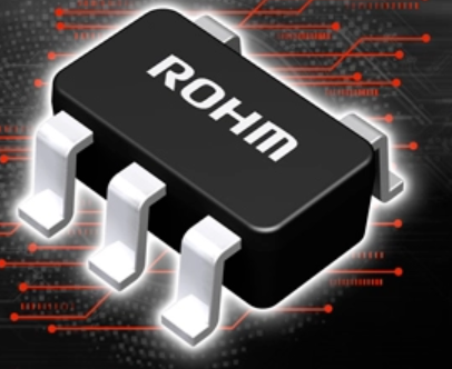
ROHM’s New Energy-Saving DC-DC Converter ICs Offered in the TSOT23 Package
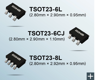
  ROHM has developed four new compact DC-DC step-down converter ICs suitable for consumer and industrial applications, including refrigerators, washing machines, PLCs, and inverters. ROHM is expanding the lineup which includes the BD9E203FP4-Z, a 2A buck converter with switching frequency of 350kHz.  In recent years, increasing application functionality in consumer devices and industrial equipment is driving the demand to minimize board space, resulting in a rise in the adoption rate of compact DC-DC converter ICs.  Furthermore, as reducing standby power consumption is becoming a significant challenge, there is a growing need for DC-DC converter ICs to deliver higher efficiency during light load (low power) conditions. To meet these demands, ROHM developed products that achieve higher efficiency in an even smaller package than existing SOP-J8 (JEDEC standard: SOIC8 equivalent) products.  The new converter ICs deliver an output current of 1A to 3A in the compact TSOT23 package (2.8mm × 2.9mm). This reduces component area by up to 72% compared to the general SOP-J8 package (4.9mm × 6.0mm), contributing to the miniaturization of power supply blocks. On top, adopting a flip chip on lead frame TSOT23 package design enables high-efficiency operation by eliminating bond wire resistance.  The BD9E105FP4-Z, BD9E202FP4-Z, and BD9E304FP4-LBZ also utilize a COT control mode during light load operation. As a result, efficiency during light load operation is improved over standard products, making them ideal for applications requiring low standby power consumption.  Going forward, ROHM will continue to focus on developing products that leverage analog design technologies, contributing to greater miniaturization and energy efficiency in consumer and industrial equipment applications.  Application Examples3.3V/5V/12V/24V power supply applications  Consumer Appliances:  Refrigerators, washing machines, air conditioners, etc.  Industrial Equipment:  PLCs (Programmable Logic Controllers), inverters, AC servos, etc.  Online Sales InformationSales Start Date: March 2024 (in succession)  Pricing: $3.0/unit (samples, excluding tax)  Online Distributors: DigiKey, Mouser and Farnell  The products will be offered at other online distributors as they become available.  Product Information  In addition to the ICs, evaluation boards together with various support tools are available that enable immediate evaluation during application design.  Various Support Tools• Calculation Sheet:A calculation tool for application circuits that facilitates external constant design. By setting values as described, users will be able to determine the circuit parameters that satisfy the desired characteristics.  The sheet is available for download from the ‘Tools’ section on each product page on ROHM’s website.  [BD9E105FP4-Z / BD9E304FP4-LBZ / BD9A201FP4-LBZ]  • ROHM Solution Simulator:A free simulation tool that runs on ROHM’s website. Changing the external constants in the topology described in the datasheet allows the optimal solution for frequency response (for a power supply) to be considered.  [BD9E105FP4-Z / BD9E202FP4-Z / BD9E304FP4-LBZ / BD9A201FP4-LBZ]  *Logging in to MyROHM is required to use the tool.  • Other Content: SPICE models for circuit simulation along with application notes that contain useful information on thermal design, circuit design, and verification can also be downloaded from each product page.  TerminologyCOT (Constant ON Time) Control Method  A feedback circuit control method for stabilizing the output voltage. When the feedback voltage drops below the reference voltage, the switching element turns ON, then automatically turns OFF after a fixed time has elapsed. This enables stable output to be efficiently obtained at light loads.  Spurious  Unnecessary electromagnetic waves that deviate from the originally required predetermined frequency.  Overshoot Prevention Function  If the output current of the power supply IC exceeds the expected value, the output is shut down by the OCP (overcurrent protection) function. When recovering from a shutdown, a momentary overshoot (excessive output voltage) occurs, causing a delay in recovery, so it is necessary to expedite recovery and suppress overshoot.  ESD (Electrostatic Discharge)  Static electricity (surge) is generated when electrically charged objects come into contact with each other. This static electricity (surge) may cause circuits and equipment to malfunction or destruction.  EMI (Electromagnetic Interference)  EMI is used as an indicator for how much noise is generated when operating the target product, which may cause problems in surrounding ICs and systems. ‘Good EMI characteristics’ mean that less noise is generated.
Key word:
Release time:2024-04-26 13:43 reading:218 Continue reading>>
NOVOSENSE at Automotive World Korea 2024: Enabling Automakers to Create Smarter, Safer Vehicles
  NOVOSENSE Microelectronics, a global provider of highly robust & reliable analog and mixed signal chip, today announced it will demonstrate the newest additions to its solutions in automotive OBC/DC-DC, traction inverter, BMS, body control module, lighting and thermal management system at the Automotive World Korea from April 24 to 26 at booth D122 in COEX Hall B, Seoul. During exhibition, NOVOSENSE engineer will give presentation about its automotive solutions on April 25.  Empowering engineers' automotive system design with product innovation  NOVOSENSE will showcase how its innovative products can help automakers to develop smarter and safer automotive system:  To support the trends of multi-node, high-speed, and high-stability in-vehicle communication, NOVOSENSE's automotive-grade CAN SIC, NCA1462-Q1, can achieve a transmission rate of ≥8Mbps in a star network, and maintain good signal quality with high EMC performance and patented ringing suppression function.  More channels are integrated on a single LED driver chip to support the increasing number of LED beads. NOVOSENSE's LED driver integrates up to 24 channels on a single chip, supporting stronger current driving capability and complete circuit protection functions.  Thermal management systems are transitioning from distributed architectures to integrated architectures. NOVOSENSE's highly integrated small motor driver SoC, NSUC1610, realizes efficient, real-time control of motor applications by integrating an ARM core MCU, a 4-way half-bridge driver, and a LIN interface on a single chip. It is widely used in electronic expansion valves, AGS, and electronic air vents.  Proven record and automotive-qualified  Since the launch of its first automotive chip in 2016, NOVOSENSE has always adhered to the “Reliable & Robust” quality policy and implemented Automotive Electronics Council (AEC)’s standards throughout the whole process. With its forward-looking product layout, robust quality performance and proven delivery record, NOVOSENSE has been widely recognized: it obtained ASIL-D certification, the highest level of the TÜV Rheinland ISO 26262 Functional Safety Management System in 2021, and joined the AEC as a member of the Component Technical Committee in 2023.  With over 10 years’ semiconductor design & mass production experience, NOVOSENSE can offer about 1,800 chip products for sale, and automotive application accounts for about 30% of NOVOSENSE revenue in 2023. NOVOSENSE has built partnership with thousands customers worldwide, including many global automotive OEMs and Tier 1/Tier 2 suppliers.
Key word:
Release time:2024-04-25 11:39 reading:352 Continue reading>>
ROHM Group Company SiCrystal and STMicroelectronics Expand Silicon Carbide Wafer Supply Agreement
  Kyoto, Japan and Geneva, Switzerland, April 22, 2024 – ROHM (TSE: 6963) and STMicroelectronics (NYSE: STM), a global semiconductor leader serving customers across the spectrum of electronics applications, announced today the expansion of the existing multi-year, long-term 150mm silicon carbide (SiC) substrate wafers supply agreement with SiCrystal, a ROHM group company. The new multi-year agreement governs the supply of larger volumes of SiC substrate wafers manufactured in Nuremberg, Germany, for a minimum expected value of $230 million.  Geoff West, EVP and Chief Procurement Officer, STMicroelectronics, commented “This expanded agreement with SiCrystal will bring additional volumes of 150mm SiC substrate wafers to support our devices manufacturing capacity ramp-up for automotive and industrial customers worldwide. It helps strengthen our supply chain resilience for future growth, with a balanced mix of in-house and commercial supply across regions”.  “SiCrystal is a group company of ROHM, a leading company of SiC, and has been manufacturing SiC substrate wafers for many years. We are very pleased to extend this supply agreement with our longstanding customer ST. We will continue to support our partner to expand SiC business by ramping up 150mm SiC substrate wafer quantities continuously and by always providing reliable quality”. said Dr. Robert Eckstein, President and CEO of SiCrystal, a ROHM group company.  Energy-efficient SiC power semiconductors enable electrification in the automotive and industrial sectors in a more sustainable way. By facilitating more efficient energy generation, distribution and storage, SiC supports the transition to cleaner mobility solutions, lower emissions industrial processes and a greener energy future, as well as more reliable power supplies for resource-intensive infrastructure like data centers dedicated to AI applications.  About STMicroelectronics  At ST, we are over 50,000 creators and makers of semiconductor technologies mastering the semiconductor supply chain with state-of-the-art manufacturing facilities. An integrated device manufacturer, we work with more than 200,000 customers and thousands of partners to design and build products, solutions, and ecosystems that address their challenges and opportunities, and the need to support a more sustainable world. Our technologies enable smarter mobility, more efficient power and energy management, and the wide-scale deployment of cloud-connected autonomous things. We are committed to achieving our goal to become carbon neutral on scope 1 and 2 and partially scope 3 by 2027.  Further information can be found at www.st.com .  About ROHM  Founded in 1958, ROHM provides ICs and discrete semiconductor devices characterized by outstanding quality and reliability for a broad range of markets, including automotive, industrial equipment and consumer market via its global development and sales network.  In the analog power field, ROHM proposes the suitable solution for each application with power devices such as SiC and driver ICs to maximize their performance, and peripheral components such as transistors, diodes, and resistors.  Further information on ROHM can be found at www.rohm.com .  About SiCrystal  SiCrystal, a ROHM group company, is one of the global market leaders for monocrystalline silicon carbide wafers. SiCrystal’s advanced semiconductor substrates provide the basis for the highly efficient use of electrical energy in electric vehicles, fast charging stations, renewable energies and in various fields of industrial applications.  Further information on SiCrystal can be found at www.sicrystal.de .
Key word:
Release time:2024-04-24 11:10 reading:336 Continue reading>>

Turn to

/ 220

  • Week of hot material
  • Material in short supply seckilling
model brand Quote
CDZVT2R20B ROHM Semiconductor
RB751G-40T2R ROHM Semiconductor
BD71847AMWV-E2 ROHM Semiconductor
TL431ACLPR Texas Instruments
MC33074DR2G onsemi
model brand To snap up
BU33JA2MNVX-CTL ROHM Semiconductor
TPS63050YFFR Texas Instruments
BP3621 ROHM Semiconductor
ESR03EZPJ151 ROHM Semiconductor
IPZ40N04S5L4R8ATMA1 Infineon Technologies
STM32F429IGT6 STMicroelectronics
Hot labels
ROHM
IC
Averlogic
Intel
Samsung
IoT
AI
Sensor
Chip
About us

Qr code of ameya360 official account

Identify TWO-DIMENSIONAL code, you can pay attention to

AMEYA360 mall (www.ameya360.com) was launched in 2011. Now there are more than 3,500 high-quality suppliers, including 6 million product model data, and more than 1 million component stocks for purchase. Products cover MCU+ memory + power chip +IGBT+MOS tube + op amp + RF Bluetooth + sensor + resistor capacitance inductor + connector and other fields. main business of platform covers spot sales of electronic components, BOM distribution and product supporting materials, providing one-stop purchasing and sales services for our customers.