NOVOSENSE Introduces the NSIP605x Series of Cost-Effective Push-Pull Transformer Drivers to Support Customers' Diverse and Flexible Designs
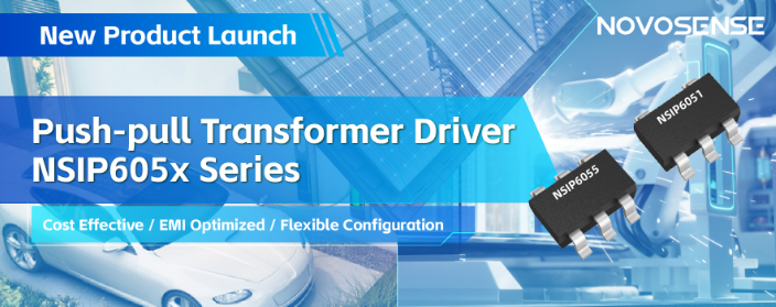
  NOVOSENSE today announced the launch of the NSIP605x series of cost-effective push-pull transformer drivers, consisting of NSIP6051 with an output power of 1W and NSIP6055 with an output power of 5W. NSIP6055 is available in two versions: NSIP6055A with a switching frequency of 160kHz, for system applications with more stringent EMI requirements; and NSIP6055B with a switching frequency of 420kHz, for system applications that require improved conversion efficiency and reduced transformer size.  The cost-effective NSIP605x series is designed for cost-sensitive systems with no particular requirements for footprint size, and offers a higher cost effectiveness than comparable devices with internally integrated transformers while providing similar system performance. The NSIP605x series complements NOVOSENSE's existing product portfolio and supports customers' diverse system design needs with flexible, lightweight configurations in a wide range of industrial, automotive and renewable energy applications.  Excellent EMI and ESD performance helps reduce system design time  Thanks to NOVOSENSE's proven EMI optimization technology, the NSIP605x series achieves ultra-low noise and EMI through slew rate control of output switching voltage and spread spectrum clocking (SSC), and the peripheral circuit requires only simple configuration to meet CISPR25 Class 5 requirements. In terms of ESD performance, NSIP605x achieves ±8kV ESD (HBM) and ±2kV ESD (CDM) performance. Excellent EMI and ESD characteristics enable customers to complete overall system debugging more quickly and easily, shortening design time.  NOVOSENSE's extensive product portfolio meets different design needs  The NSIP605x series of push-pull transformer drivers is a new addition to the cost-effective product line introduced by NOVOSENSE. NOVOSENSE also offers a selection of other high-performance, highly-integrated products, including: the NSIP88/89xx series and the NIRSP31x series with integrated transformers and multi-channel digital isolators; the NSIP83086 series of isolated RS485 transceivers and the NSIP1042 series of isolated CAN transceivers, integrated with transformers and isolation interfaces. NOVOSENSE's comprehensive product portfolio can meet the diverse system design needs of various types of customers, providing one-stop semiconductor solutions for different customers.
Key word:
Release time:2024-05-21 17:27 reading:243 Continue reading>>
NOVOSENSE Introduces New Solid State Relays: Supporting 1700V Withstand Voltages and Meeting CISPR25 Class 5 Requirements
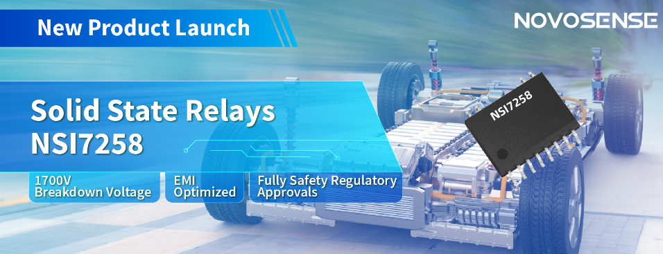
  Building on its long history in isolation technology, NOVOSENSE today announced the launch of its new NSI7258 series of capacitive isolation-based solid state relays, available in both industrial and automotive grades. Designed specifically for high-voltage measurement and insulation monitoring, NSI7258 provides industry-leading voltage withstand capability and EMI performance to help improve the reliability and stability of high-voltage systems such as industrial BMS, PV, energy storage, charging piles, and BMS and OBCs for new energy vehicles.  Integrated SiC MOSFETs, supporting 1700V withstand voltages  High-voltage systems are becoming increasingly prevalent in both the industrial and automotive sectors. In order to match the trend of high-voltage industrial and automotive platforms, NSI7258 integrates two SiC MOSFETs developed with NOVOSENSE's participation in a back-to-back format, each supporting up to 1700V withstand voltages; in the standard 1-minute avalanche test, NSI7258 withstands an avalanche voltage of 2100V and an avalanche current of 1mA, achieving industry-leading voltage and avalanche resistance. At the same time, under the test conditions of 1000V high voltage and 125°C high temperature, the leakage current of NSI7258 can be controlled within 1μA, which greatly improves the insulation impedance and detection accuracy of the battery pack in the BMS and enables safer human-machine interaction.  Compliance with various safety requirements, reducing system verification time  The popularity of high-voltage applications requires compliance with various stringent safety requirements. With NOVOSENSE's proprietary technology, NSI7258 achieves industry-leading creepage distance of 5.91mm on the secondary side and 8mm on the primary side in a SOW12 package, which meets the requirements of IEC60649 formulated by the International Electrotechnical Commission (IEC). In addition, with NOVOSENSE's superior capacitive isolation technology, NSI7258's voltage withstand capability is up to 5kVrms, which fully meets the relevant UL, CQC and VDE certifications, reducing customers' system verification time and accelerating the product-to-market process.  Significant EMI optimization, accelerating optocoupler relay replacement  Traditional optocoupler relay solutions suffer from light decay problems and their performance degrades over time, but the advantage of optocoupler relays is that they have no EMI problems, which is one of the important factors limiting optocoupler replacement in high-voltage systems. NOVOSENSE's NSI7258 is cleverly designed to achieve industry-leading EMI performance, easily passing the CISPR25 Class 5 test without magnetic beads on the single board and leaving sufficient margin in the full-band test. NSI7258 is produced based on an all-semiconductor process for higher reliability in long-term use. Superior EMI performance and increased reliability allow customers to use multiple devices in the system at the same time without being affected, significantly reducing design difficulty and enabling customers to accelerate optocoupler replacement in system designs.
Key word:
Release time:2024-05-20 15:39 reading:358 Continue reading>>
What is a Radio Frequency Integrated Circuit
  From smartphones and wireless internet access to radar and navigation systems, radio frequency (RF) transmission technology is making the world increasingly interconnected. With the continuous advancement of this technology, Radio Frequency Integrated Circuits (RFICs) themselves have become complex chips that also need to be integrated into System-on-Chip (SoC) solutions. RFICs are designed to operate at high frequencies, typically within the range of several hundred megahertz to several gigahertz.  The goal of RF circuit design is to send and receive signals between the source and destination with acceptable quality without incurring high costs. This can be achieved through the use of validated design methodologies in circuit design. RFICs typically incorporate amplifiers, filters, mixers, oscillators, and modulation/demodulation functions on a single chip.  RF circuit design is a hybrid technology that simultaneously employs both low-frequency analog design methods and microwave circuit design methods. The primary difference between microwave design and low-frequency analog design lies in the importance of transmission line principles. Microwave design relies heavily on the concept of transmission lines, whereas low-frequency analog design does not. Therefore, choices of impedance levels and descriptions such as signal magnitude, noise, and distortion are affected.  What is RFIC?At its core, an RFIC is a specialized type of integrated circuit (IC) designed to operate at high frequencies, typically within the radio frequency (RF) spectrum. These circuits are meticulously engineered to handle the unique challenges posed by high-frequency signals, making them indispensable components in a wide array of applications, from smartphones and Wi-Fi routers to radar systems and satellite communication.  Main components of RFIC design  Antenna: Used for transmitting and receiving radio frequency signals.  Filters: Filters out signals in specific frequency bands. It includes bandpass filters (BPF) that allow a specific frequency range to pass through, low-pass filters (LPF) that allow frequencies lower than a specific frequency to pass through, and high-pass filters (HPF) that allow frequencies higher than a specific frequency to pass through.  Impedance Matching: Matches the source impedance and load impedance to minimize signal reflection or enhance power transmission.  Low-Noise Amplifier (LNA): Amplifies weak signals and filters out noise responses (as the received signal is not strong enough to pass directly through the mixer).  Modulator: Used for signal modulation. It encodes the signal in a certain way to meet the requirements of the communication channel. It can act as an “up-converter” in the transmitter, where it combines the low-frequency analog signal with the local oscillator signal to generate an RF signal.  Demodulator: Decodes the received signal. It extracts the signal carrying the original information from the modulated carrier.  Power Amplifier: Used to amplify the output of the mixer to a higher power for transmission. The higher the transmission efficiency, the wider the coverage range.  RF Switch: Allows high-frequency signals to pass through specific transmission channels.  Use and Advantages of RFICWireless Communication and Connectivity: RFICs are widely used in wireless communication in fields such as smartphones, Internet of Things (IoT) devices, and household appliances. Devices that support RFICs have become an indispensable part of daily life. Their key advantages lie in compact integration, power management, and high-speed data transmission.  Automotive Radar Systems: RFICs can be used in automotive radar systems for applications such as collision prevention, adaptive cruise control, and parking assistance. With their compact size, they can easily be installed in vehicles, thereby enhancing safety.  Wireless Sensor Networks: RFICs can be used in wireless sensor networks for applications such as environmental monitoring, smart agriculture, and industrial automation. Wireless connections between sensor nodes eliminate the need for extensive wiring and infrastructure. RFIC applications offer flexibility and scalability as they are easy to expand or reconfigure based on RFIC-based networks.  Satellite Communication: RFICs can be used for tasks such as signal amplification, frequency conversion, and modulation in satellite communication systems. Extensive coverage, high data transmission rates, and efficient signal processing are just some of their many advantages.  Difference between RFIC and MMICRFICs (Radio Frequency Integrated Circuits) and MMICs (Monolithic Microwave Integrated Circuits) are both specialized types of integrated circuits designed for high-frequency applications, but they have distinct characteristics and applications.  Frequency Range: The primary distinction between RFICs and MMICs lies in their operating frequency range. RFICs operate in the lower RF frequency range, while MMICs operate in the higher microwave frequency range.  Applications: RFICs are typically used in consumer electronics and telecommunications applications that operate at lower frequencies, while MMICs are employed in high-frequency and microwave systems that require superior performance and bandwidth.  Design Focus: RFICs are designed with a focus on integration, low power consumption, and cost-effectiveness for mass-market applications. In contrast, MMICs prioritize performance, high-frequency operation, and signal integrity, often targeting specialized or niche markets with demanding requirements.  What is the frequency of RFIC?The frequency range of RFICs (Radio Frequency Integrated Circuits) can vary widely depending on the specific application and design requirements. RFICs are typically designed to operate within the radio frequency (RF) spectrum, which spans from a few kilohertz (kHz) to several hundred gigahertz (GHz).  Common frequency bands for RFICs include:  Low Frequency RFICs: These RFICs operate in the lower RF frequency range, typically spanning from a few megahertz (MHz) to several hundred megahertz (MHz). They are commonly used in applications such as AM/FM radio receivers, RFID (Radio Frequency Identification), and some wireless sensor networks.  Medium Frequency RFICs: RFICs operating in the medium frequency range typically cover frequencies from several hundred megahertz (MHz) to a few gigahertz (GHz). This range includes common wireless communication standards like Bluetooth, Wi-Fi, Zigbee, and cellular networks (2G, 3G, 4G LTE).  High Frequency and Microwave RFICs: These RFICs operate in the higher frequency range, spanning from a few gigahertz (GHz) up to several hundred gigahertz (GHz). They are used in applications such as radar systems, satellite communication, microwave links, and high-speed data transmission.  ConclusionRadio Frequency Integrated Circuits (RFICs) stand as the unsung heroes of modern connectivity, bridging the gaps between devices, networks, and people. Through relentless innovation and ingenuity, RFIC technology has transformed the landscape of wireless communication, shaping the way we live, work, and interact in the digital age.
Key word:
Release time:2024-05-16 11:48 reading:275 Continue reading>>
GigaDevice Launches New Low-power MCU products of GD32L235 series
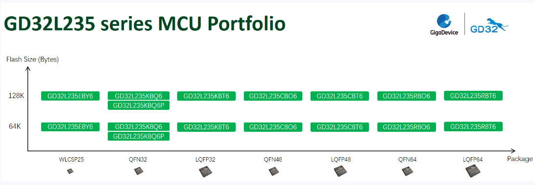
  Beijing, China (Thursday, May 14, 2024) - GigaDevice (stock code 603986), a leading semiconductor company specializing in Flash Memory, 32-bit Microcontrollers (MCUs), Sensors, and Power Management technologies, has officially launched the GD32L235 series MCU, further enriching the selection of low-power products and reinforcing its presence in this market segment. The brand-new GD32L235 product series is designed to meet the needs of the low-power market segment. With enhanced power consumption efficiency, rich interface resources, and superior cost performance, it is ideal for applications including industrial metering, smart door locks, portable devices, IoT, e-cigarettes, and BMS. Offering a total of 16 model options across seven packages, including LQFP64/48/32, QFN64/48/32, and WLCSP25, the GD32L235 series MCUs have commenced official mass production and distribution.  The GD32L235 series MCUs have optimized and improved power consumption efficiency and support six low-power modes, including Deep-sleep, Sleep, Standby, etc. In Deep-sleep mode, the current drops to 1.8uA, and the wakeup time is less than 2uS; in Standby mode, the current is as low as 0.26uA. Even under full-speed operating mode with maximum clock frequency, power consumption is only at 66uA/MHz, achieving an excellent balance between performance and power consumption.  The GD32L235 series MCUs use the Arm® Cortex®-M23 core with a clock frequency of 64MHz. In addition, they are equipped with 64KB to 128KB embedded flash memory and 12KB to 24KB SRAM. These MCUs are divided into two models based on storage capacity to cater to the varied requirements of users across different application scenarios. This series integrates two 16-bit low-power timers, six general-purpose 16-bit timers, one advanced timer, two basic timers, two low-power LPUARTs, two USARTs, two UARTs, three I2Cs, two SPIs, and other general peripheral interfaces, as well as standard communication interfaces such as one CAN2.0 controller and one USB2.0 FS controller. In terms of analog peripherals, this series is equipped with one 12-bit ADC supporting both differential and single-ended input modes, improving the accuracy and performance of the ADC module. Additionally, it integrates one 12-bit DAC and two comparators. The GD32L235 series offers the option of WLCSP25 ultra-small package, making it suitable for wearable consumer electronics, portable devices, and other application scenarios with limited hardware space.  The supporting documents, manuals, and software resources of the GD32L235 series are available in GD32MCU.com for users to download and utilize. Development tools tailored for various packages and pin configurations of the GD32L235 series have also been released. These include the GD32L235R-EVAL full-featured evaluation board and entry-level learning kits such as GD32L235O-START, GD32L235Q-START, and GD32L235E-START, providing users with convenient development and debugging experiences.
Key word:
Release time:2024-05-15 11:37 reading:392 Continue reading>>
Nidec Machine Tool Launches Newly Developed, Compact & Powerful Universal Head - A Light, Thin, Short and Small Product Capable of Meeting Various Machining Needs
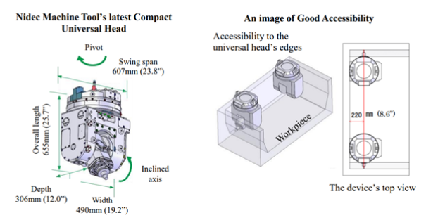
  - A Universal Head that is approximately 80% in size of conventional products but that still possesses industry-leading high-speed machining  - A Universal Head contributes to automated machining system and saves manpower of cast heavy duty cutting to high-precision mold finishing  Nidec Machine Tool Corporation (represented by Mr. Haruhiko Niitani, president, and headquartered in Ritto, Shiga Prefecture) (“Nidec Machine Tool” or the “Company”), a Nidec Group company, today announced the launch of a new universal head (UH), an attachment of the Company’s MVR series of double column type milling machine with five-face machining capability The UH boasted an industry-leading compactness, by making the size approximately 80%*1of the conventional products, while maintaining the spindle capability with high output and speed.  This small UH enables a better accessibility between the tool-and the workpiece, as well as finished-surface quality and high-efficiency machining under ideal machining conditions, and its “light, thin, short, and small” features contribute greatly to mold and other products’ manufacturing processes. This UH’s sale is going to start at the Company’s “Large Machine Preview Show” to be held in Ritto, Shiga Prefecture, on Friday, February 02.  While made compact to improve its tool-workpiece accessibility and motion range, this new UH has an inclined axis with an extended tool-holding projection, enabling a better accessibility with a workpiece and the use of short and small tools. Additionally, even in machining processes that require long tools, this UH’s stiffer main spindle makes possible a variety of machining, from rough to finish machining. Also, with the UH able to approach up to 220mm (8.6”) to the wall, thanks to an improved swing span and interference range, the interference area with a workpiece has become smaller, and it can perform the precision machining on small and thin works and deep corners.  To secure better efficiency, this UH has a spindle speed of 20-6,000min-1, a spindle motor output of 15kW/420min-1, and a spindle maximum torque of 341N·m, while enjoying shorter non-machining time based on faster indexing time of each axis, shorter machining time due to stiffer attachments, and other features to improve productivity. Furthermore, the UH, which can perform indexing per angular 1 degree even during high output, has a high degree of freedom in machining, and can capable of handling a wide range of works, from cast heavy duty cutting to high-precision mold finish machining.  This UH can be installed into the Company’s double column type milling machining with five-face machining capability, i.e., MVR·Ax and MVR·Hx. The machines already delivered to the customers are also capable to install the attachment with additional construction.  Nidec Machine Tool Corporation stays committed to making proposals to contribute to addressing manufacturing automation, manpower saving, and other issues in the fields of machinery business and total solutions including attachments and peripheral devices.
Key word:
Release time:2024-05-14 11:26 reading:273 Continue reading>>
Top 10 IC Design Houses’ Combined Revenue Grows 12% in 2023, NVIDIA Takes Lead for the First Time, Says TrendForce
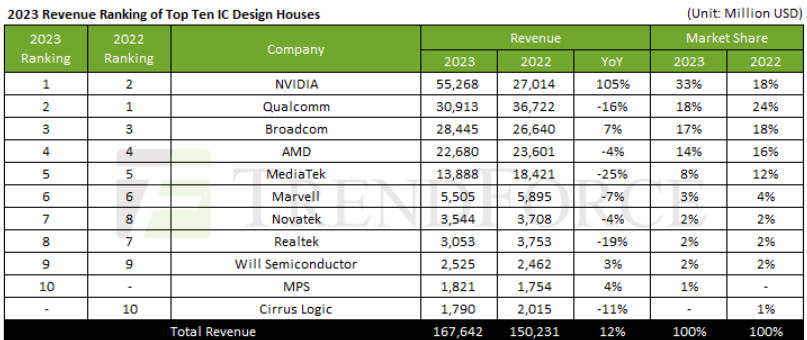
  In 2023, the combined revenue of the world’s top ten IC design houses reached approximately $167.6 billion, marking a 12% annual increase. This growth was primarily driven by NVIDIA, which saw a remarkable 105% increase in revenue, significantly boosting the overall industry. While Broadcom, Will Semiconductor, and MPS experienced only marginal revenue growth, other companies faced declines due to economic downturns and inventory reductions, says TrendForce.  Looking ahead to 2024, TrendForce predicts that with IC inventory levels returning to healthy standards and driven by the AI boom, major CSPs will continue to expand the construction of LLMs. Additionally, AI applications are expected to penetrate personal devices, potentially leading to the introduction of AI-powered smartphones and AI PCs. Consequently, the global IC design industry's revenue growth is expected to continue its upward trajectory.  NVIDIA, Broadcom, and AMD benefit from a surge in demand for AI  The top five IC design houses boosted their 2023 revenues to $55.268 billion—a 105% year-over-year increase—primarily driven by NVIDIA’s AI GPU H100. Currently, NVIDIA captures over 80% of the AI accelerator chip market, and its revenue growth is expected to continue in 2024 with the release of the H200 and next-generation B100/B200/GB200. Broadcom’s revenue reached $28.445 billion in 2023 (semiconductor segment only), growing by 7%, with AI chip income accounting for nearly 15% of its semiconductor solutions. Despite stable wireless communications revenue, Broadcom expects a near-double-digit decline in broadband and server storage connectivity this year.  AMD’s revenue fell by 4% to $22.68 billion in 2023, due to declining PC demand and inventory reductions, affecting most of its business segments. Only its data center and embedded businesses, boosted by the acquisition of Xilinx, grew by 17%. AMD’s AI GPU MI300 series, launched in the fourth quarter of 2023, is expected to be a major revenue driver in 2024.  Conversely, Qualcomm and MediaTek were impacted by the downturn in the smartphone market. Qualcomm’s 2023 revenue decreased by 16% YoY to $30.913 billion (QCT only) due to weak demand in the handheld device and IoT sectors, with China’s smartphone shipments hitting a decade low. However, Qualcomm is actively promoting the automotive market, expecting automotive revenues to more than double by 2030.  MediaTek’s revenue also fell in 2023, dropping 25% YoY to $13.888 billion, with declines in smartphone, power management IC, and smart edge businesses. Nevertheless, due to the adoption of its Dimensity 9300 by several Chinese clients and expected growth in high-end smartphone shipments, the company predicts a return to double-digit growth for all of 2024.  Two significant changes in the ranking from sixth to tenth took place: First, Cirrus Logic fell off the list from its last place spot and was replaced by MPS, whose 2023 revenue rose 4% YoY to $1.821 billion thanks to automotive, enterprise data, and storage computing businesses—offsetting declines in communication and industrial sectors.  Secondly, Realtek’s revenue fell by 19% annually to $3.053 billion in 2023, dropping the company down to eighth place. The decline was mainly due to a sharp decrease in PC shipments, a suspension of telecom tenders in China, and early inventory write-offs. However, after clearing inventory, Realtek saw a slight improvement in PC and automotive shipments in the first quarter of 2024 over networking and consumer electronics. With the launch of WiFi-7 in the third quarter, the restart of telecom tenders, and participation in the development of edge computing frameworks through the Arm alliance, Realtek’s revenues are poised for growth.
Key word:
Release time:2024-05-13 14:48 reading:391 Continue reading>>
Nidec Precision Develops TapSense, the World’s Thinnest Linear Resonant Actuator
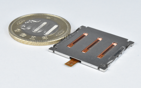
  Nidec Precision Corporation (“Nidec Precision” or the “Company”), a member of Nidec Corporation’s group companies, announced today that it has developed TapSense, the world’s thinnest linear resonant actuator*.  Nidec Precision’s TapSense  Nidec Precision developed TapSense, the world’s thinnest* 1.4mm-thick linear resonant actuator by utilizing its precision manufacturing technology that the Company has, since its foundation, nurtured in the camera industry – and by designing from scratch a magnetic circuit optimum for a thin actuator. TapSense realizes tablet and notebook PCs and other digital terminals that are thinner than their conventional models.  With its excellent responsiveness and vibration force, TapSense can reproduce a crisp click feeling, while recreating a variety of tactile feedback, including the feeling of dial control. Additionally, its high responsiveness makes TapSense easier to control than conventional linear resonant actuators.  The cumulative shipments of the Nidec Group’s vibration motors exceeded 1.5 billion units at the end of March 2024, and these motors produced by Nidec’s technologies which enable light, thin, short, and small form factors with high efficiency and ease of control are highly valued by our customers.  As a member of the world’s leading comprehensive motor manufacturer, Nidec Precision stays committed to proposing revolutionary solutions that contribute to realizing a comfortable society.  *Data, from Nidec Precision’s research, as of May 01, 2024
Key word:
Release time:2024-05-10 13:11 reading:313 Continue reading>>
A solution for automotive gear shift switch based on Hangshun chip automotive grade MCU HK32A040C8T3
  Throughout the global development of passenger cars, automatic transmission has been widely adopted. Its simple and easy to learn, convenient and intelligent characteristics bring drivers a more comfortable driving experience, and also better adapt to urban traffic.  The implementation of the automatic shift function actually uses a gear shift switch instead of manual operation. The gear shift switch will control the shift fork and gear shift based on different engine speeds, vehicle speeds, and the driver's intention to press the accelerator. To achieve these automated operations, a shift switch requires a brain.  The Hangshun chip M0 series automotive grade MCU HK32A040C8T3 is such a "brain", applied in gear shift switch schemes. Its main function is to receive signals from the gear shift switch and convert these signals into electrical signals that can control the car's engine, transmission, and other parts, thereby simplifying driving operations and providing great convenience for the driver.  In the process of developing its new generation of electric vehicles, in order to ensure that the vehicle's performance, reliability, and safety reach the optimal level, after in-depth technical evaluation and multiple rounds of screening, Selis New Energy Vehicles finally chose a gear shift switch scheme based on the Hangshun chip HK32A040C8T3.  The Selis engineering team has conducted a rigorous review of the functional characteristics, processing speed, power consumption performance, environmental adaptability, and cost-effectiveness of the Hangshun HK32A040C8T3 MCU in multiple dimensions. Hangshun's MCU has successfully conquered the engineering team with its outstanding performance, especially in high reliability and strong anti-interference ability. In addition, HK32A040C8T3 has high integration and flexible peripheral interfaces, providing engineers with greater design freedom and optimization space, making the entire electronic control system more compact and efficient.  HK32A040 using ARM ® Cortex ®- M0 core, with a maximum operating frequency of 96MHz, built-in up to 124 Kbyte Flash and 10 Kbyte SRAM. By configuring the Flash controller registers, the remapping of interrupt vectors within the main Flash area can be achieved. And it supports traditional Flash Level 0/1/2 read-write protection and Flash code encryption (patented by Hangshun).  Strong scalability  32-bit ARM CPU architecture, good ecological environment  Rich peripheral resources to meet platform expansion  Multiple packaging options available for LQFP64, LQFP48, QFN32, and QFN28  high reliability  Car specification quality, compliant with AEC-Q100 Grade 1  Complies with ISO 9001 and IATFT 16949 quality management systems  Supports -40 ℃~125 ℃  High cost performance ratio  Equal performance/resources, with higher cost-effectiveness  Quality service  Complete ecological supporting facilities  15 years of design life, with a supply chain guarantee of over 15 years  The gear shift switch scheme based on the Hangshun Vehicle Class MCU HK32A040C8T3 has been successfully applied in the Sailis new energy vehicle, which not only improves the electronic control efficiency of the entire vehicle, but also achieves lower energy consumption and better user experience.  The Hangshun chip series vehicle grade MCU HK32A040 can be widely used in vehicle domain controllers, such as doors and windows, tail lights, wipers, anti-theft alarms, car keys, air conditioning, electric seats, etc.  Hangshun Chip adheres to the strategy of SoC+32-bit high-end MCU in automotive standards. In recent years, it has invested a large amount of research and development resources in the field of automotive electronics, committed to providing the market with higher reliability and more cost-effective automotive chip solutions, helping customers achieve a win-win situation in cost control and user experience.
Key word:
Release time:2024-05-09 11:48 reading:377 Continue reading>>
Analogy Semi wins
What is a potentiometer ? Classification and function
  A potentiometer is an adjustable electronic component that serves to adjust the voltage or current in a circuit by changing the resistance value. Potentiometers are usually composed of a resistor body made of metal or carbon film and movable brushes. The contact area of the resistor body is changed by rotating or pressing the brushes to change its resistance value.  Potentiometers are commonly used in volume adjustment, brightness adjustment, frequency adjustment and other circuits, is a widely used electronic components.  What is a potentiometer?A potentiometer, often referred to as a “pot,” is a type of variable resistor used in electronic circuits. Its name is derived from “potential” and “meter.” The main function of a potentiometer is to regulate the flow of electric current by manually adjusting its resistance.  A typical potentiometer consists of a resistive element, a movable contact (usually a wiper), and three terminals. The resistive element is a track of resistive material, and the wiper makes contact with this track. The three terminals are usually labeled as “1,” “2,” and “3.” Terminals 1 and 3 are connected to the ends of the resistive track, while the wiper is connected to the terminal 2.  By turning the knob or shaft of the potentiometer, the position of the wiper along the resistive track changes, altering the resistance between the wiper (terminal 2) and the other two terminals (1 and 3). This variation in resistance allows for precise control of the voltage or current in a circuit.  Potentiometers are commonly used for tasks such as volume control in audio equipment, brightness control in electronic displays, and tuning in radios. They come in different types and sizes, each suited to specific applications.  How many types of potentiometer are there?  There are several types of potentiometers, each designed for specific applications and requirements. The main types include:  Linear Potentiometers:  The resistance along the track changes linearly with the rotation of the shaft. These are commonly used in applications where a linear relationship between the knob position and the output is required, such as volume controls.  Logarithmic Potentiometers (Log or Audio Taper):  The resistance changes logarithmically with the rotation of the shaft. These are often used in audio applications, like volume controls for human ears perceive loudness logarithmically.  Multi-Turn Potentiometers:  These pots have multiple turns of the shaft, providing greater precision and control. They are used in applications where fine adjustments are critical.  Single-Turn Potentiometers:  These have a single rotation of the shaft and are suitable for applications where a full range of adjustment can be achieved with one complete turn.  Wirewound Potentiometers:  The resistive element is made of a wire wound around an insulating core. These pots are known for their durability and precision and are often used in applications requiring high power handling.  Cermet Potentiometers:  The resistive element is made of a ceramic and metal mixture. Cermet pots are known for their stability and reliability, especially in terms of temperature variations.  Digital Potentiometers:  Instead of a mechanical knob, these use digital signals to adjust resistance. They are often used in digitally controlled circuits for electronic adjustments.  Motorized Potentiometers:  These pots have a motor-driven mechanism for remote or automated adjustments, often controlled by a feedback system.  What is the function of the potentiometer?The potentiometer serves the primary function of varying the resistance in an electrical circuit, and this adjustable resistance finds application in several ways.  The main purpose of a potentiometer is to control the voltage in an electrical circuit by varying the resistance. Here are some common uses of potentiometers:  Volume Control: Potentiometers are frequently used in audio devices, such as amplifiers and stereos, to adjust the volume. Turning the potentiometer knob changes the resistance, altering the volume level.  Brightness Control: In electronic devices like televisions and monitors, potentiometers can be used to adjust the brightness of the display.  Variable Voltage Divider: Potentiometers can function as variable voltage dividers in circuits, allowing the user to set a specific voltage level by adjusting the resistance.  Motor Speed Control: Potentiometers are employed in some motor control circuits to regulate the speed of motors by adjusting the voltage supplied to them.  Sensor Calibration: Potentiometers are utilized in sensors and transducers for calibration purposes. They allow users to fine-tune the sensitivity or offset of a sensor.  Tuning in Electronic Circuits: Potentiometers are used in tuning circuits to adjust the frequency or other parameters in radio receivers and other communication devices.  Temperature Control: In some electronic devices, potentiometers can be employed for temperature control by adjusting the resistance in temperature-sensitive circuits.  User Interface Control: Potentiometers are found in user interfaces, such as rotary knobs on electronic devices, where users can interactively adjust settings.  How to choose the right potentiometer?  Selecting the right potentiometer needs to consider the following aspects:  1, Parameters: you need to choose the right resistance value, maximum operating voltage, maximum operating current and other parameters according to the actual application.  2, The adjustment mode: according to the use of customary selection of rotary or straight slide potentiometer.  3、Linearity:Linearity refers to the proportionality between the output voltage or current of the potentiometer and the input voltage or current. For applications that require precise adjustment, choose a potentiometer with better linearity.  4, Precision: the precision of the potentiometer refers to the accuracy of its output resistance, usually expressed in terms of error. For applications requiring high-precision adjustment, choose a potentiometer with higher precision.  5, life: potentiometer life refers to the time it can work normally. For applications that require long-term use, choose a potentiometer with a longer life.  6, Package form: according to the application to choose the appropriate package form, such as direct insertion, chip type, etc..
Key word:
Release time:2024-05-06 15:01 reading:261 Continue reading>>

Turn to

/ 220

  • Week of hot material
  • Material in short supply seckilling
model brand Quote
MC33074DR2G onsemi
BD71847AMWV-E2 ROHM Semiconductor
TL431ACLPR Texas Instruments
RB751G-40T2R ROHM Semiconductor
CDZVT2R20B ROHM Semiconductor
model brand To snap up
STM32F429IGT6 STMicroelectronics
BU33JA2MNVX-CTL ROHM Semiconductor
TPS63050YFFR Texas Instruments
ESR03EZPJ151 ROHM Semiconductor
BP3621 ROHM Semiconductor
IPZ40N04S5L4R8ATMA1 Infineon Technologies
Hot labels
ROHM
IC
Averlogic
Intel
Samsung
IoT
AI
Sensor
Chip
About us

Qr code of ameya360 official account

Identify TWO-DIMENSIONAL code, you can pay attention to

AMEYA360 mall (www.ameya360.com) was launched in 2011. Now there are more than 3,500 high-quality suppliers, including 6 million product model data, and more than 1 million component stocks for purchase. Products cover MCU+ memory + power chip +IGBT+MOS tube + op amp + RF Bluetooth + sensor + resistor capacitance inductor + connector and other fields. main business of platform covers spot sales of electronic components, BOM distribution and product supporting materials, providing one-stop purchasing and sales services for our customers.